background image

7

IMPORTANT: Excessive running of the
electric starter could damage the starter due
to overheating. To prevent possible damage,
do not run electric starter more than 10 times
at intervals of 5 seconds ON, 5 seconds OFF.
Then wait more than 40 minutes to allow
starter to cool before continuing to run
starter. Before repeating engine starting
procedure, check that ignition key switch is
ON, and make sure there is fresh fuel in fuel
tank. If engine continues to fail to start,
servicing may be needed.

5.

RECOIL STARTING—Hold snowthrower with
one hand and pull recoil starter vigorously with
other hand.

6.

When engine starts, push in choke slowly.

7.

TO ENGAGE ROTOR—Squeeze control bar to
handle. When the control bar handle is released,
the rotor blades stop, but the engine continues to
run.

8.

TO STOP ENGINE—Release control bar to stop
rotor, turn key to OFF, and wait for all moving
parts to stop before leaving operator’s position.

Operating Tips (Fig. 9)

1.

ADJUSTING DISCHARGE CHUTE 
Rotate chute crank clockwise to move discharge
chute to the right and counterclockwise to move
chute to the left. The chute deflector handle on
top of the discharge chute controls the height of
the snow stream. Do not overtighten the chute
deflector mounting nuts so excessive force is
required to adjust the deflector.

2.

SELF–PROPELLING ACTION — The
snowthrower clears down to the ground and
propels itself forward when the handle is raised
and the snowthrower is tilted slightly forward so
rotor blades strike the ground. The wheels do not
have to touch the ground in order to self-propel.
The further you tilt the handle forward, the faster
the snowthrower self-propels. However, depth

and height of snow affects forward speed.
Always overlap each swath and discharge
downwind whenever possible.

POTENTIAL HAZARD

When engine is running, discharge rotor is
turning.

WHAT CAN HAPPEN

Objects thrown from discharge chute can
cause personal injury.

HOW TO AVOID THE HAZARD

Keep yourself and other people away from
discharge opening when engine is running.

Before leaving operating position, stop
engine by turning key to OFF.

3.

Keep the area to be cleared free of stones, toys or
other foreign objects which may be picked up
and thrown by the rotor blades. Such items could
be covered by snowfall and, therefore, unnoticed
until struck by the rotor blades. Always be sure
to keep children and pets away from area of
operation.

4.

Should you find it necessary to clear snow from
crushed rock or gravel, push down on handle to
raise rotor blades clear of loose material that
could be thrown by the blades.

5.

In some snow and cold weather conditions, some
controls and moving parts may freeze solid.
Therefore, when any control becomes hard to
operate, stop the engine. Check all parts for
excessive freeze up. DO NOT USE
EXCESSIVE FORCE WHEN TRYING TO
OPERATE FROZEN CONTROLS.
 Free all
controls and moving parts before operating.

6.

AFTER CLEARING SNOW — Let engine run
for a few minutes so ice does not freeze moving
parts solid. After engine is shut off, wipe ice and
snow off entire unit. Operate chute crank several
times to clear mechanism of snow.

Summary of Contents for 38430

Page 1: ...Operator s Manual FORM NO 3319 424 CCR 3000 GTS Snowthrower Model No 38430 8900001 Up Model No 38435 8900001 Up ...

Page 2: ...The engine exhaust from this product contains chemicals known to the State of California to cause cancer birth defects or other reproductive harm WARNING ...

Page 3: ...ed in USA i Figures 637 1 Model and serial number decal 637 1 2 3 Unit shown on right side 1 Short spacer 2 Long spacer 3 Pushnut 893 635 3 1 2 4 1 Chute crank 2 Mounting bracket 3 Gear 4 Plastic bushing 1 2 636 1 Chute ring 2 Discharge chute 1 2 3 4 ...

Page 4: ...5 1 Eyebolt 2 Control bar bracket 3 Rear hole 111 1 2 3 1 Add oil to small amount of gasoline 2 Install cap and shake can to mix 3 Add remaining amount of gasoline 1 2 3 5 4 6 642 1 Key switch 2 Primer 3 Recoil start 4 Choke 5 Elec start button 6 Cord connection ELEC START MODEL 5 6 7 8 ...

Page 5: ...iii 2 3 1 629 1 Chute crank 2 Chute deflector handle 3 Deflector mounting nuts 1 2 630 1 Spring cover 2 Cable adjuster 634 1 16 1 1 Scraper 2 644 1 1 Scraper 2 Carriage bolts locknuts 9 10 11 12 ...

Page 6: ... Long self tapping screw 4 Short self tapping screws 4 2 1 6 3 5 626 1 Engine pulley 2 Idler pulley 3 Roller 4 Brake arm assembly 5 Rotor pulley 6 Belt guide 643 1 2 1 Control panel 2 Mounting screws 1 628 1 Spark plug wire 0 032 0 81 mm 110 13 14 15 16 17 ...

Page 7: ...v 1 1 Wear indicator hole 1 2 3 4 4 5 6 7 8 680 1 Rotor blade 2 2 Rotor half 2 3 Torx screw 8 4 Locknut 13 5 Hex head capscrew 4 6 Spacer 4 7 Auger shaft assembly 8 Hex head screw 18 19 ...

Page 8: ...vi 1 2 3 681 1 Thin layer 2 Thick layer 3 Wear indicator hole 20 ...

Page 9: ...factory always know the model and serial numbers of your product These numbers will help the Service Dealer or Service Representative provide exact information about your specific product You will find the model and serial number decal located in a unique place on the product Fig 1 For your convenience write the product model and serial numbers in the space below Model No Serial No Read this manua...

Page 10: ...nly after reading this manual 3 Keep everyone especially children and pets away from snowthrower and area of operation 4 Inspect area thoroughly where snowthrower will be used Remove doormats sleds boards sticks wire and any other foreign objects which might be picked up and thrown by the snowthrower 5 Keep all shields and safety devices in place If a shield safety device or decal is illegible dam...

Page 11: ...ossible damage an obstruction or loose parts Vibration is generally a sign of trouble Repair any damage before operating snowthrower again 21 Before adjusting cleaning repairing or inspecting the snowthrower or before unclogging the discharge chute stop engine by turning key to OFF and wait for all moving parts to stop Do not make adjustments while engine is running 22 WHENEVER YOU LEAVE THE OPERA...

Page 12: ...cer and a wheel onto the right axle end The side of the wheel with six spokes must face the center of the machine 3 Slide a pushnut onto the end of the axle 4 Using a hammer strike the pushnut to seat the nut FIRMLY in place 5 Turn the machine over on its right side so that the left axle end is pointing up 6 For the left side slide the long spacer and a wheel onto the left axle end The side of the...

Page 13: ... Adjusting Control Bar page 8 Note The control cable must always have slack in it when in the disengaged position Before Starting POTENTIAL HAZARD In certain conditions gasoline is extremely flammable and highly explosive WHAT CAN HAPPEN A fire or explosion from gasoline can burn you others and cause property damage HOW TO AVOID THE HAZARD Use a funnel and fill the fuel tank outdoors in an open ar...

Page 14: ...he engine during operation and prevents gum like varnish deposits from forming in the engine during periods of storage IMPORTANT NEVER USE METHANOL GASOLINE CONTAINING METHANOL GASOHOL CONTAINING MORE THAN 10 ETHANOL PREMIUM GASOLINE OR WHITE GAS BECAUSE ENGINE FUEL SYSTEM DAMAGE COULD RESULT DO NOT USE FUEL ADDITIVES OTHER THAN THOSE MANUFACTURED FOR FUEL STABILIZATION DURING STORAGE SUCH AS TORO...

Page 15: ...ghtly forward so rotor blades strike the ground The wheels do not have to touch the ground in order to self propel The further you tilt the handle forward the faster the snowthrower self propels However depth and height of snow affects forward speed Always overlap each swath and discharge downwind whenever possible POTENTIAL HAZARD When engine is running discharge rotor is turning WHAT CAN HAPPEN ...

Page 16: ...10 Unhook lower cable end from adjuster Reposition cable end in a higher or lower hole on adjuster to obtain a gap of 1 16 1 8 between control bar bracket and handle Positioning cable end in a lower hole decreases gap positioning cable end in a higher hole increases gap Reinstall upper cable end into rear hole in control bar bracket hole with arrow Fig 6 Slide spring cover over cable adjuster and ...

Page 17: ...ig 15 17 Before each snow season check the spark plug If electrodes in center of plug are dark or have deteriorated install a new plug Use an NGK BPMR4A spark plug and set gap at 032 81 mm 1 REMOVE CONTROL PANEL Fig 15 Remove 3 capscrews securing control panel to housing Remove ignition key and lift off panel allowing it to hang on recoil rope 2 REMOVE SPARK PLUG Fig 16 Pull wire off spark plug an...

Page 18: ...capscrews 2 spacers and 2 locknuts Fig 19 Position bolt heads on thick bottom side of blade Curve the blade and secure it with the remaining 4 torx screws and locknuts position screw heads on thick side of blade Tighten all screws and nuts securely Storage 1 FUEL SYSTEM PREPARATION Add Toro Stabilizer Conditioner to the fuel tank one ounce per gallon of fuel Run engine for five minutes to distribu...

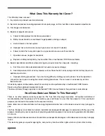
Page 19: ...t Must You Do To Keep The Warranty In Effect You must maintain your TORO GTSĆ5 Engine by following the maintenance schedule detailed in the operator s manual at your expense You must record this work in the maintenance chart provided in your owner s manual and keep your proof of purchase How Do You Get Service If the starting performance of your TORO GTSĆ5 Engine should diminish to the point where...

Page 20: ...heck the operator s manual to ensure you are using the correct starting procedures This can save an unnecessary visit to a Service Dealer All warranty repairs reimbursable under this warranty must be performed by an Authorized TORO Service Dealer using Toro approved replacement parts The above remedy through repair by an Authorized TORO Service Dealer is the purchaser s sole remedy How Does State ...

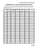
Page 21: ...wing maintenance after every 25 operating hours more often in dusty and dirty conditions Follow the procedures in this Operator s Manual and record information on this chart Date Hours Used Change Oil Air Cleaner Service Lubricate Wheels Check Spark Plug Storage Doesn t Apply to 2 Cycle Mowers only Mowers only ...

Page 22: ...tility lawn garden equipment engines are warranted for two years from the date of delivery If any emission related part on your engine is defective in materials or workmanship the part will be repaired or replaced by Toro free of charge Owner s Warranty Responsibilities As the engine owner you are responsible for the performance of the required maintenance listed in your owner s manual Toro recomm...

Page 23: ...anted part which is scheduled for replacement as required maintenance shall be warranted for the period of time up to the first scheduled replacement point for that part Coverage under this warranty extends only to the parts listed below the emissions system parts to the extent that these parts were present on the engine when purchased Fuel Metering System Cold start enrichment system including th...

Page 24: ...warranty validation The owner shall not be charged for diagnostic labor which leads to the determination that a warranted part is defective if the diagnostic work is performed at a warranty station The Toro Company is not liable for indirect incidental or consequential damages in connection with the use of the TORO Products covered by this warranty except for damages to other engine components cau...

Page 25: ...17 ...

Page 26: ...18 ...

Page 27: ...19 ...

Page 28: ...ept WPM Toro Customer Service Department 8111 Lyndale Avenue South Bloomington MN 55420 1196 612 888 8801 800 348 2424 What Must You Do To Keep The Warranty In Effect You must maintain your TORO Product by following the mainĆ tenance procedures described in the operator s manual Such routine maintenance whether performed by a dealer or by you is at your expense What Does This Warranty Not Cover an...

Reviews: