background image

The Toro Warranty

Conditions and Products Covered

The Toro Company and its affiliate, Toro Warranty Company, pursuant to
an agreement between them, jointly promise to the original purchaser*
to repair the Toro Products listed below if defective in materials or
workmanship.

The following time periods apply from the date of purchase:

Products

Warranty Period

Walk Power Mowers

Cast Deck

5 years Residential Use

2

45 Days Commercial Use

Engine

5 years GTS Promise
See engine manufacturer's warranty

1

Steel Deck

2 years Residential Use

2

45 Days Commercial Use

Engine

2 years GTS Promise
See engine manufacturer's warranty

1

Electric Hand Held Products

2 year limited warranty

Snowthrowers

Single Stage

2 years Residential Use

2

45 Days Commercial Use

Two Stage

2 years Residential Use

2

45 Days Commercial Use

Electric

2 years Residential Use

2

All Ride-On Units Below

Engine

See engine manufacturer's warranty

1

1 year Parts only

Attachments

1 year

Rear Engine Riders

2 years Residential Use

2

90 Days Commercial Use

Lawn & Garden Tractors

2 years Residential Use

2

90 Days Commercial Use

TimeCutter Z Mowers

3 years Residential Use

2

30 Days Commercial Use

TITAN Mowers

3 years or 240 hours

3

Frame

Lifetime (original owner only)

4

TITAN MX Mowers

3 years or 400 hours

3

Frame

Lifetime (original owner only)

4

Z Master Mowers — 2000 Series

5 years or 1200 hours

3

Frame

Lifetime (original owner only)

4

*Original Purchaser means the person who originally purchased the Toro Product.

1

Some engines used on Toro Products are warranted by the engine manufacturer.

2

Residential use means use of the product on the same lot as your home. Use at more than one

location is considered commercial use and the commercial use warranty would apply.

3

Whichever occurs first.

4

Lifetime Frame Warranty - If the main frame, consisting of the parts welded together to form the

tractor structure that other components such as the engine are secured to, cracks or breaks in

normal use, it will be repaired or replaced, at Toro's option, under warranty at no cost for parts

and labor. Frame failure due to misuse or abuse and failure or repair required due to rust or

corrosion are not covered.

This warranty includes the cost of parts and labor, but you must pay
transportation costs.

Warranty may be denied if the hour meter is disconnected, altered, or
shows signs of being tampered with.

Owner Responsibilities

You must maintain your Toro Product by following the maintenance
procedures described in the

Operator's Manual

. Such routine

maintenance, whether performed by a dealer or by you, is at your expense.

Instructions for Obtaining Warranty Service

If you think that your Toro Product contains a defect in materials or
workmanship, follow this procedure:

1.

Contact your seller to arrange service of the product. If for any
reason it is impossible for you to contact your seller, you may contact
any Toro Authorized Distributor to arrange service.

2.

Bring the product and your proof of purchase (sales receipt) to the
Service Dealer. If for any reason you are dissatisfied with the Service
Dealer’s analysis or with the assistance provided, contact us at:

Customer Care Department, RLC Division
The Toro Company
8111 Lyndale Avenue South
Bloomington, MN 55420-1196
Manager: Technical Product Support: 001–952–887–8248

See attached Distributor List

Items and Conditions Not Covered

This express warranty does not cover the following:

Cost of regular maintenance service or wear parts, such as blades,
rotor blades (paddles), scraper blades, belts, fuel, lubricants, oil
changes, spark plugs, cable/linkage or brake adjustments

Any product or part which has been altered or misused and requires
replacement or repair due to accidents or lack of proper maintenance

Repairs necessary due to failure to use fresh fuel (less than one
month old), or failure to properly prepare the unit prior to any period
of non-use over one month

Engine and transmission. These are covered by the appropriate
manufacturer’s guarantees with separate terms and conditions

All repairs covered by these warranties must be performed by an
Authorized Toro Service Dealer using Toro approved replacement parts.

General Conditions

The purchaser is covered by the national laws of each country. The rights
to which the purchaser is entitled with the support of these laws are not
restricted by this warranty.

374-0268 Rev C

Summary of Contents for 38828 Power Max HD 1128 OXE

Page 1: ...s manual identifies potential hazards and has safety messages identified by the safety alert symbol Figure 2 which signals a hazard that may cause serious injury or death if you do not follow the recommended precautions Figure 2 1 Safety alert symbol This manual uses 2 words to highlight information Important calls attention to special mechanical information and Note emphasizes general information...

Page 2: ... Checking the Engine Oil Level 21 Checking and Adjusting the Skids 21 Checking and Adjusting the Traction Cable 21 Checking the Auger Gearbox Oil Level 22 Changing the Engine Oil 22 Adjusting the Discharge Chute Latch 23 Replacing the Drive Belts 24 Replacing the Headlight Bulb 24 Storage 25 Preparing the Machine for Storage 25 Removing the Machine from Storage 25 Troubleshooting 26 2 ...

Page 3: ...ring operation or while performing an adjustment or repair Operation Do not put hands or feet near or under rotating parts Keep clear of the discharge opening at all times Exercise extreme caution when operating on or crossing gravel drives walks or roads Stay alert for hidden hazards or traffic After striking a foreign object stop the engine remove the wire from the spark plug thoroughly inspect ...

Page 4: ...loose fitting clothing that could get caught in moving parts If a shield safety device or decal is damaged illegible or lost repair or replace it before beginning operation Also tighten any loose fasteners Do not smoke while handling gasoline Do not use the machine on a roof Do not touch the engine while it is running or soon after it has stopped because the engine may be hot enough to cause a bur...

Page 5: ... turn control 3 Warning read the Operator s Manual 5 Cutting dismemberment hazard impeller keep away from moving parts remove the ignition key and read the instructions before servicing or performing maintenance 7 Auger impeller drive squeeze the lever to engage release the lever to disengage 2 Traction drive squeeze the lever to engage release the lever to disengage 4 Cutting dismemberment hazard...

Page 6: ...nhalation hazard 2 Warning fire hazard 4 Warning hot surface burn hazard Briggs Stratton Part No 277566 1 When starting a cold engine close the choke and press the primer two times 2 When starting a warm engine open the choke and do not press the primer Briggs Stratton Part No 277588 1 Primer 3 Ignition key out Engine Stop 2 Ignition key in Engine Run Briggs Stratton Part No 278866 1 Fuel On 2 Fue...

Page 7: ...parts required Check the skids 9 No parts required Check the operation of the traction drive 1 Installing the Upper Handle Parts needed for this procedure 4 Handle bolts 4 Curved washers 4 Locknuts Procedure Note Do not remove the rubber band on the cables until you have installed the upper handle 1 Lift and rotate the upper handle and position it over the lower handle Figure 3 Important Route the...

Page 8: ...install the washer and the nut and hand tighten the nut Figure 7 Figure 7 1 Cable clamp 2 Important Ensure that the curved side of the cable clamp is against the handle and that the cable is routed below the clamp bolt The cable must be in a straight line from the cable clamp to the point where it attaches to the wheel clutch lever 4 Pull the cable jacket down gently until the wheel clutch lever i...

Page 9: ...ter that you previously removed 3 Remove the hairpin cotter and the outer washer from the trunnion on the upper end of the speed control rod Figure 11 Figure 11 1 Speed selector lever 3 Inner washer 2 Trunnion 4 Outer washer Note To make installation easier leave the flat washer on the trunnion Figure 11 4 Shift the speed selector lever into Position R2 5 Rotate the lower link arm fully upward cou...

Page 10: ... back end of the long chute control rod with the flattened front end of the short rod that extends from the control panel so that they nest together Figure 14 g018656 Figure 14 1 Short rod 2 Long chute control rod 4 Insert the front end of the rod into the opening in the back of the chute gear cover until it slides into the chute gear Figure 15 Figure 15 5 Align the holes in the nested ends of the...

Page 11: ...our machine comes with oil in the engine crankcase Note Before starting the engine check the oil level and add oil if necessary Use automotive detergent oil with an API service classification of SF SG SH SJ SL or higher Refer to your engine owner s manual Use Figure 18 below to select the best oil viscosity for the outdoor temperature range expected Figure 18 1 Using SAE 30 at outdoor temperatures...

Page 12: ...ed causing injury and or property damage Carefully check the traction drive and adjust it properly if necessary 1 Start the engine refer to Starting the Engine 2 Move the speed selector to Position R1 refer to Operating the Speed Selector 3 Squeeze the left hand traction lever to the hand grip Figure 20 Figure 20 The machine should move rearward If the machine does not move or moves forward comple...

Page 13: ...s when the traction lever is in the released position check the traction cable refer to Checking and Adjusting the Traction Cable or take the machine to an Authorized Service Dealer for service Product Overview Figure 21 1 Hand grip 2 10 Scraper 2 Auger impeller lever 11 Auger 3 Speed selector lever 12 Skid 2 4 Quick Stick discharge chute control 13 Electric starter button 5 Traction lever 14 Elec...

Page 14: ... an octane rating of 87 or higher R M 2 rating method Oxygenated fuel with up to 10 ethanol or 15 MTBE by volume is acceptable Do Not use ethanol blends of gasoline such as E15 or E85 with more than 10 ethanol by volume Performance problems and or engine damage may result which may not be covered under warranty Do Not use gasoline containing methanol Do Not store fuel either in the fuel tank or fu...

Page 15: ...e throttle to the Fast position Figure 29 Figure 29 7 Start the machine pulling the recoil starter or pressing the electric starter button Figure 30 Figure 30 1 Electric starter button 3 Recoil starter 2 Electric starter plug Note To use the electric starter connect a power cord to the electric starter plug first and then to a power outlet Important To prevent damaging the electric starter run it ...

Page 16: ...tion 3 Remove the ignition key 4 Close the fuel shutoff valve by rotating it clockwise Figure 32 Figure 32 5 Pull the recoil starter 3 or 4 times This helps prevent the recoil starter from freezing up Operating the Traction Drive CAUTION If the traction drive is not properly adjusted the machine may move in the direction opposite of what you intended causing injury and or property damage Carefully...

Page 17: ...ore easily when the engine is not running Operating the Speed Selector The speed selector has 6 forward and 2 reverse gears To change speeds release the traction lever and shift the speed selector lever to the desired position Figure 36 The lever locks in a notch at each speed selection Figure 36 Operating the Auger Impeller Drive 1 To engage the auger impeller drive squeeze the right hand auger i...

Page 18: ...wn on the handles to raise the front of the machine a few inches centimeters off the pavement Then lift the handles quickly to bump the front of the machine on the pavement Repeat if necessary until a stream of snow comes out the discharge chute If you cannot unclog the discharge chute by bumping the front of the machine stop the engine wait for all moving parts to stop and use the snow clean out ...

Page 19: ... feet and any other part of your body or clothing away from concealed moving or rotating parts WARNING The rotor blades can throw stones toys and other foreign objects and cause serious personal injury to the operator or to bystanders Keep the area to be cleared free of all objects that the rotor blades could pick up and throw Keep all children and pets away from the area of operation Always set t...

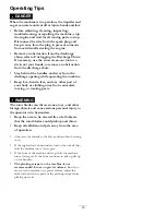
Page 20: ...ect the traction cable and adjust or replace it if necessary Check the auger gearbox oil and add oil if necessary Yearly or before storage Check the air pressure in the tires and inflate them to 17 20 psi 116 137 kPa Drain the gasoline and run the engine to dry out the fuel tank and the carburetor at the end of the season Have an Authorized Service Dealer inspect and replace the traction drive bel...

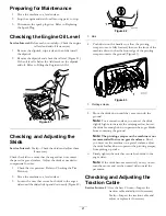
Page 21: ...ntil the skids slide up and down easily Figure 42 Figure 42 1 Skid 4 Push down on the handles to allow the pivoting scraper to move fully forward then set the front of the machine down so that the front edge of the pivoting scraper contacts the ground Figure 43 Figure 43 1 Pivoting scraper 5 Move the skids down until they are even with the ground Note For a smooth surface you can set the skids sli...

Page 22: ... 1 Move the machine to a level surface 2 Clean the area around the pipe plug Figure 46 Figure 46 3 Remove the pipe plug from the gearbox 4 Check the oil level in the gearbox The oil should be at the point of overflowing at the filler opening 5 If the oil level is low add GL 5 or GL 6 SAE 85 95 EP transmission oil to the gearbox until the point of overflow Note Do not use synthetic oil 6 Install th...

Page 23: ... at a local recycling center 4 Install the oil drain cap 5 Fill the crankcase with oil Refer to Filling the Engine Crankcase with Oil Adjusting the Discharge Chute Latch If the discharge chute does not lock into the desired position or does not unlock so that you can move it to another position adjust the discharge chute latch 1 Remove the fastener on the gear cover Figure 49 lift the front of the...

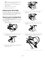
Page 24: ...lt Replacing the Headlight Bulb Use a GE 892 16W halogen light bulb Do not touch the bulb with your hands or allow dirt or moisture to come into contact with the bulb 1 Remove the wire connector from the back of the headlight Figure 52 Figure 52 2 Turn the base of the bulb counterclockwise until it stops Figure 53 Figure 53 3 Remove the bulb straight out from the back of the headlight Figure 54 Fi...

Page 25: ...the spark plug wire 12 Remove the spark plug add 1 oz 30 ml of oil through the spark plug hole and pull the starter rope slowly several times to distribute oil throughout the cylinder to prevent cylinder corrosion during the off season 13 Loosely install the spark plug 14 Dispose of any unused fuel properly Recycle it according to local codes or use it in your automobile Note Do not store stabiliz...

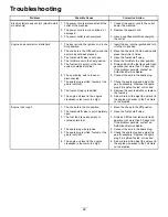
Page 26: ...ct the wire to the spark plug 7 The spark plug is pitted fouled or the gap is incorrect 7 Check the spark plug and adjust the gap if necessary Replace the spark plug if it is pitted fouled or cracked 8 The fuel vent cap is restricted 8 Remove the vent restriction or replace the fuel cap Engine does not start or starts hard 9 The engine oil level in the engine crankcase is too low or too high 9 Add...

Page 27: ...just the auger impeller drive belt refer to www Toro com for servicing information or take the machine to an Authorized Service Dealer Engine runs but the machine discharges snow poorly or not at all 7 The auger impeller drive belt is worn or broken 7 Replace the auger impeller drive belt refer to www Toro com for servicing information or take the machine to an Authorized Service Dealer Discharge ...

Page 28: ...Notes 28 ...

Page 29: ...Notes 29 ...

Page 30: ...s We will not use personal information provided for warranty purposes for marketing nor shall we give or sell personal information provided for warranty purposes to any other company for marketing We reserve the right to disclose personal information in order to comply with applicable laws and with requests by the appropriate authorities to operate its systems properly or for our own protection or...

Page 31: ...14 347 9479 Hydroturf Egypt LLC Egypt 202 519 4308 Ibea S P A Italy 39 0331 853611 Irriamc Portugal 351 21 238 8260 Irrigation Products Int l Pvt Ltd India 86 22 83960789 Jean Heybroek b v Netherlands 31 30 639 4611 Maquiver S A Colombia 57 1 236 4079 Maruyama Mfg Co Inc Japan 81 3 3252 2285 Metra Kft Hungary 36 1 326 3880 Mountfield a s Czech Republic 420 255 704 220 Munditol S A Argentina 54 11 ...

Page 32: ...use or abuse and failure or repair required due to rust or corrosion are not covered This warranty includes the cost of parts and labor but you must pay transportation costs Warranty may be denied if the hour meter is disconnected altered or shows signs of being tampered with Owner Responsibilities You must maintain your Toro Product by following the maintenance procedures described in the Operato...

Reviews: