Product Overview
G020177
4
3
2
1
8 15
9
10
11
12
13
6
5
14
7
5
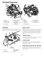
Figure 4
1.
Deflector
5.
Motion control levers
9.
Engine
13.
Anti-scalp roller
2.
Rear drive wheel
6.
Operator seat
10.
Engine guard
14.
Smart Speed
™
lever
3.
Height of cut lever
7.
Foot assist lever (certain
models only)
11.
Mower deck
15.
Hydraulic reservoir
4.
Control panel
8.
Gas tank cap
12.
Front caster wheel
Controls
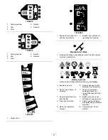
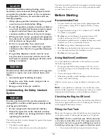
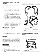
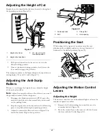
Become familiar with all of the controls in Figure 4 and
Figure 5 before you start the engine and operate the machine.
Figure 5
Control Panel
1.
Throttle
3.
Blade control switch
(power take-off)
2.
Ignition switch
4.
Choke
Ignition Switch
The ignition switch has three positions, Off, Run and Start.
The key will turn to Start and move back to Run upon release.
Turning the key to the Off position will stop the engine;
however, always remove the key when leaving the machine
to prevent someone from accidentally starting the engine
(Figure 5).
Throttle Control
The throttle controls the engine speed and it has a continuous
variable setting from Slow to Fast (Figure 5).
Choke Control
Pull up on the Choke control until it stops to choke the
engine (Figure 5). Push down on the Choke control for
normal engine operation
Blade Control Switch (Power Take-Off)
The blade control switch, represented by a power take-off
(PTO) symbol, engages and disengages power to the mower
blades (Figure 5).
13
Summary of Contents for 74395
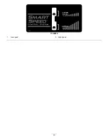
Page 10: ...119 8874 1 Low speed 2 High speed 10 ...
Page 50: ...Schematics g017655 Electrical Diagram Rev A 50 ...
Page 51: ...Notes 51 ...


