4
1
2
G014970
3
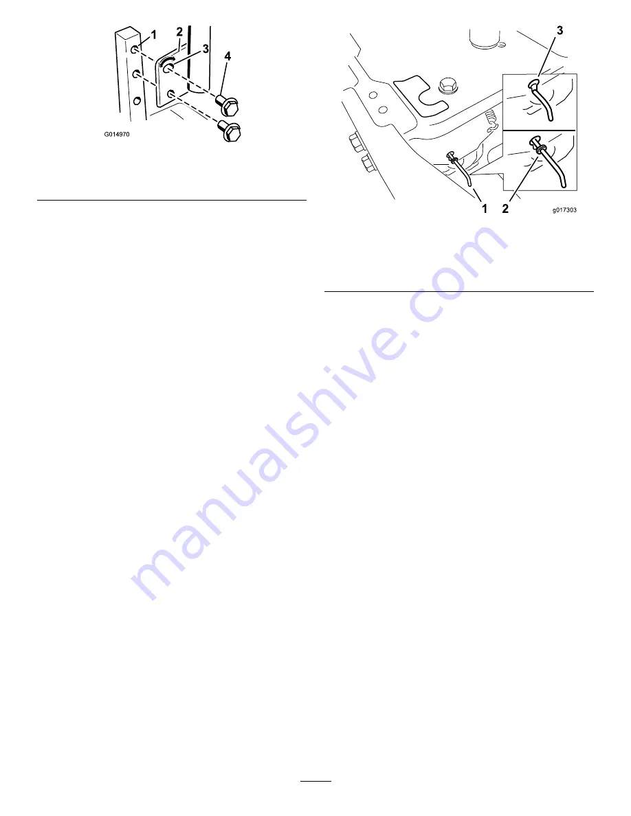
Figure 24
1.
Control arm shaft
3.
Slotted, upper hole
2.
Control lever
4.
Bolt
3.
Repeat the adjustment for the opposite control lever.
Adjusting the Tilt
The motion control levers can be tilted fore or aft for
maximum operator comfort.
1.
Loosen the upper bolt holding the control lever to the
control arm shaft.
2.
Loosen the lower bolt just enough to pivot the control
lever fore or aft (Figure 24). Tighten both bolts to
secure the control in the new position.
3.
Repeat the adjustment for the opposite control lever.
Pushing the Machine by Hand
Important:
Always push the machine by hand. Never
tow the machine because damage may occur.
This machine has an electric brake mechanism and to push
the machine the ignition key needs to be in the Run position.
The battery needs to be charged and functioning for the
electric brake to be disengage.
To Push the Machine
1.
Park the machine on a level surface and disengage the
blade control switch.
2.
Move the motion control levers outward to park
position, stop the engine, and wait for all moving parts
to stop before leaving the operating position.
3.
Locate the bypass levers on the frame on both sides of
the engine.
4.
Move the bypass levers forward through the key hole
and down to lock them in place as shown in Figure 25 .
Ensure this is done for each lever.
5.
Move the motion control levers inward to the neutral
position and turn the ignition key to the run position.
Do not start the machine.
The machine is now able to be pushed by hand.
g017303
1 2
3
Figure 25
1.
Bypass lever location
3.
Lever position for pushing
the machine
2.
Lever position for
operating the machine
6.
When finished, ensure the key has been returned to the
Stop position to avoid draining the battery charge.
If the machine fails to move the electric brake may still be
engaged. If necessary the electric brake can be released
manually. Refer to the Releasing the Electric Brake (page 35)
procedure in Drive Maintenance.
To Operate the Machine
Move the bypass levers rearward through the key hole and
down to lock them in place as shown in Figure 25. Ensure
this is done for each lever.
22
Summary of Contents for 74395
Page 10: ...119 8874 1 Low speed 2 High speed 10 ...
Page 50: ...Schematics g017655 Electrical Diagram Rev A 50 ...
Page 51: ...Notes 51 ...


