4.
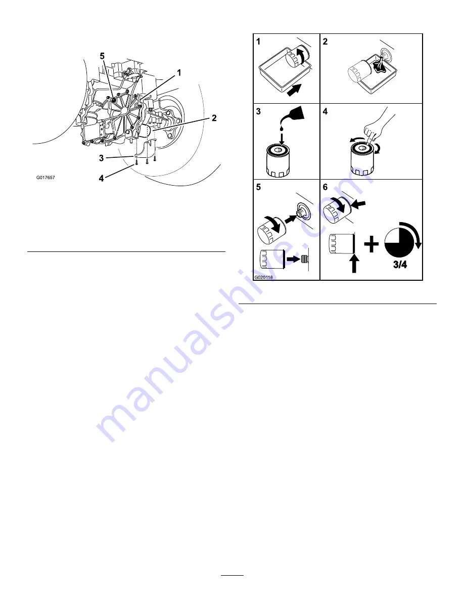
Locate the filter and filter guards on each transaxle
drive system (Figure 50). Remove three screws securing
the filter guard and guard.
G017657
5
1
2
3
4
Figure 50
Right side shown
1.
Transaxle drive
4.
Screws
2.
Oil filter
5.
Vent plug
3.
Filter guard
5.
Carefully clean area around filters. It is important that
no dirt or contamination enter hydraulic system.
6.
Place a container below the filter to catch the oil that
drains when the filter and vent plugs are removed.
7.
Locate and remove the vent plug on each transmission
8.
Unscrew the filter to remove and allow oil to drain
from drive system.
Repeat this procedure for both filters.
Installing the Hydraulic System Filters
1
2
3
4
5
6
3/4
G0201 18
Figure 51
1.
Apply a thin coat of the specified oil on the surface of
the rubber seal of each filter.
2.
Turn the filter clockwise until rubber seal contacts the
filter adapter then tighten the filter an additional 3/4 to
1 full turn. Repeat for the other filter
3.
Install the filter guards over each filter as previously
removed. Use the three screws to secure the filter
guards.
4.
Install the transaxle support. Refer to Figure 49 for the
correct torque values for the nuts and bolts.
Note:
Ensure the transaxle support is installed (Figure
5.
Verify the vent plugs are removed before adding the oil.
6.
Slowly pour the specified oil through expansion
reservoir until oil comes out of
one
of the vent plug
holes. Stop and install that vent plug. Torque the plug
to 180 in-lb (20.3 N-m).
7.
Continue to add oil through the expansion reservoir
until oil comes out of the remaining vent plug hole on
the second transmission. Stop and install that vent
plug. Torque the plug to 180 in-lb (20.3 N-m).
8.
Continue to add oil through the expansion reservoir
until it reaches the FULL COLD line on the expansion
reservoir.
37
Summary of Contents for 74395
Page 10: ...119 8874 1 Low speed 2 High speed 10 ...
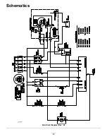
Page 50: ...Schematics g017655 Electrical Diagram Rev A 50 ...
Page 51: ...Notes 51 ...

