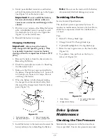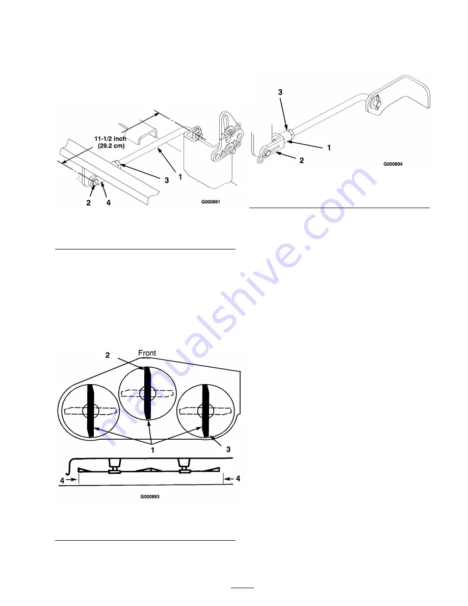
pin from the end of the rod (Figure 44),
loosen the jam nut, and turn the yoke until the
11-1/2 inch (29.3 cm) dimension is obtained.
7. Then secure the yoke with the clevis pin and
cotter pin. Repeat this procedure on the
opposite side of the mower.
Figure 44
1. Rear trunion rod
3. Jam nut
2. Clevis pin and cotter pin
4. Yoke
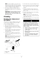
8. Set the height-of-cut at 3 inch (76 mm) and
carefully rotate the blades so they are facing
front to rear (Figure 45).
9. Measure between the tip of the front blade
(Figure 45) and the tip of the rear blade to
the flat surface. If the front blade tip is not
1/16-5/16 inch (1.6-7.9 mm) lower than the
rear blade tip, adjust the front trunion rods.
Figure 45
1. Blade front to rear
3. Measure rear blade tip
2. Measure front blade tip
4. Measure here
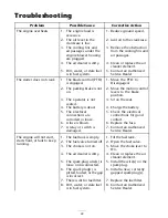
10. To adjust the front-to-rear blade slope, remove
the hairpin cotter from the front trunion yokes
and loosen the jam nuts (Figure 46).
Figure 46
1. Front trunion rod yoke
3. Jam nut
2. Hairpin cotter
11. Rotate the yokes on the rods to change the
adjustment (Figure 46). To raise the front
of the mower, tighten the yokes (shorten the
rods). To lower the front of the mower, loosen
the yokes (lengthen the rods).
12. After adjusting both trunion rod yokes evenly,
secure the yokes with the hairpin cotters.
Check the front-to-rear level again. Continue
adjusting the yokes until the front blade tip is
1/16-5/16 inch (1.6-7.9 mm) lower than the
rear blade tip (Figure 45).
13. When the front-to-rear blade slope is correct,
tighten the jam nuts (Figure 44 and Figure 46).
14. Recheck the side-to-side level of the mower;
refer to Leveling the Mower from Side-to-Side.
15. Check the height of the anti-scalp rollers; refer
to Adjusting the Anti-Scalp Rollers.
Removing the Mower
1. Park the machine on a level surface.
2. Disengage the PTO and move the control
levers to the neutral locked position and apply
the parking brake.
3. Stop the engine, remove the key, and wait for
all moving parts to stop before leaving the
operating position.
4. Lower the height-of-cut lever to the lowest
position.
33
Summary of Contents for 74806 TimeCutter ZX525
Page 7: ...Slope Chart 7 ...
Page 41: ...Schematics Electrical Schematic Rev A 41 ...
Page 42: ...Notes ...
Page 43: ...Notes ...


