background image

Figure 57

1.

Blade

2.

Balancer

Installing the Blades

1. Install the blade onto the spindle shaft (Figure 55).

Important:

The curved part of the blade must

be pointing upward toward the inside of the
mower to ensure proper cutting.

2. Install the spring disk and blade bolt. The spring

disk cone must be installed toward the bolt head
(Figure 55). Torque the blade bolt to 100-110 ft-lb
(135-150 N-m).

Mower Deck Leveling

Check to ensure the mower deck is level any time you
install the mower or when you see an uneven cut on
your lawn.

The mower deck must be checked for bent blades
prior to leveling; any bent blades must be removed
and replaced. Refer to the Checking for Bent Blades
procedure before continuing.

The mower deck must be leveled side-to-side first then
the front to rear slope can be adjusted.

Requirements:

The machine must be on a level surface.

All four tire must be properly inflated. Refer to
Checking the Tire Pressure in the Drive System
Maintenance section.

Checking Side-to-Side Level

The mower blades must be level from side to side.
Check the side-to-side level any time you install the
mower or when you see an uneven cut on your lawn.

1. Park the machine on a level surface and disengage

the blade control switch.

2. Move the motion control levers outward to the

neutral lock position, stop the engine, remove the
key, and wait for all moving parts to stop before
leaving the operating position.

3. Carefully rotate the blades side to side.

4. Measure between the outside cutting edges and

the flat surface (Figure 58). If both measurements

are not within 3/16 inch (5 mm), an adjustment is
required; continue to the Leveling procedure.

Figure 58

1.

Blades side to side

3.

Measure from the tip of the
blade to the flat surface
here

2.

Outside cutting edges

Checking the Front-to-Rear Blade
Slope

Check the front-to-rear blade level any time you install
the mower. If the front of the mower is more than
5/16 inch (7.9 mm) lower than the rear of the mower,
adjust the blade level using the following instructions:

1. Park the machine on a level surface and disengage

the blade control switch.

2. Move the motion control levers outward to the

neutral position, engage the parking brake, stop the
engine, remove the key, and wait for all moving parts
to stop before leaving the operating position.

3. Carefully rotate the blades so they are facing front

to rear (Figure 59).

4. Measure from the tip of the front blade to the flat

surface and the tip of the rear blade to the flat surface
(Figure 59). If the front blade tip is not 1/16-5/16
inch (1.6-7.9 mm) lower than the rear blade tip,
continue to the Leveling the Mower Deck procedure.

42

Summary of Contents for 74833

Page 1: ...ITAN ZX6030 Zero Turn Radius Riding Mower Model No 74833 Serial No 310000001 and Up G009968 To register your product or download an Operator s Manual or Parts Catalog at no charge go to www Toro com O...

Page 2: ...o meet safety emission and operating requirements the actual engine horsepower on this class of lawn mower will be significantly lower Introduction Read this information carefully to learn how to oper...

Page 3: ...5 Operating Tips 25 Maintenance 27 Recommended Maintenance Schedule s 27 Premaintenance Procedures 28 Raising the Seat 28 Lubrication 28 Greasing the Bearings 28 Engine Maintenance 29 Servicing the Ai...

Page 4: ...aution when making turns Look behind and to the side before changing directions Never leave a running machine unattended Always turn off blades set parking brake stop engine and remove key before dism...

Page 5: ...approaching blind corners shrubs trees the end of a fence or other objects that may obscure vision Towing A hitch kit is available for this machine and can be obtained by contacting an Authorized Toro...

Page 6: ...fety and instruction decals as necessary Use only genuine Toro replacement parts to ensure that original standards are maintained Toro Riding Mower Safety The following list contains safety informatio...

Page 7: ...degrees Use the slope chart to determine the degree of slope of hills before operating Do not operate this machine on a slope greater than 15 degrees Fold along the appropriate line to match the recom...

Page 8: ...ass lever position for pushing the machine 115 9631 1 Power take off PTO Blade control switch on some models 5 Fast 2 Blade control switch On 6 Continuous variable setting 3 Blade control switch Off 7...

Page 9: ...of hand or foot stay away from moving parts 112 9840 1 Read the Operator s Manual 3 Remove the ignition key and read the instructions before servicing or performing maintenance 2 Height of cut 117 119...

Page 10: ...ng maintenance apply parking brake remove the ignition key and disconnect the spark plug wire 3 Thrown object hazard keep bystanders a safe distance from the machine pick up debris before operating ke...

Page 11: ...4 Check the hydraulic oil every 25 hours 2 Check the engine oil every 8 hours 5 Check the caster wheel tire pressure every 25 hours 3 Check the drive wheel tire pressure every 25 hours 6 Lubricate th...

Page 12: ...4 Fuel gauge 7 Anti scalp roller 10 Control panel 2 Operator seat 5 Footrest 8 Deflector 3 Parking brake 6 Front caster wheel 9 Foot pedal deck lift and height of cut G010009 1 2 3 4 5 6 Figure 5 1 Ga...

Page 13: ...re 6 Fuel Gauge The fuel window located below the operator position can be used to verify the level of gasoline in the tank Figure 7 G010016 G010077 1 Figure 7 1 Fuel gauge window Motion Control Lever...

Page 14: ...avoid injury DANGER Mowing on wet grass or steep slopes can cause sliding and loss of control Wheels dropping over edges can cause rollovers which may result in serious injury death or drowning A loss...

Page 15: ...tay away from an open flame or where gasoline fumes may be ignited by a spark Store gasoline in an approved container and keep it out of the reach of children Never buy more than a 30 day supply of ga...

Page 16: ...when mixed with fresh gasoline To minimize the chance of varnish deposits in the fuel system use fuel stabilizer at all times Gasoline Alcohol blends Gasohol up to 10 percent ethyl alcohol 90 percent...

Page 17: ...igure 11 Releasing the Parking Brake G010079 1 2 Figure 12 Operating the Throttle The throttle control can be moved between Fast and Slow positions Figure 13 Always use the fast position when turning...

Page 18: ...ve the motion controls outward to the neutral lock position Figure 16 3 Set the parking brake Figure 16 refer to Setting the Parking Brake 4 Move the blade control switch PTO to the Off position Figur...

Page 19: ...e 19 Disengaging the Blade Control Switch PTO G009174 Figure 20 The Safety Interlock System WARNING If safety interlock switches are disconnected or damaged the machine could operate unexpectedly caus...

Page 20: ...he seat engage the parking brake move the blade control switch to Off and lock the motion control levers in neutral Start the engine While the engine is running center the motion controls and move for...

Page 21: ...actor while it is unattended Always remove the ignition key and set the parking brake when leaving the machine unattended even if just for a few minutes Adjusting the Height of Cut The machine is equi...

Page 22: ...k removal 2 Cut height pin 5 Lock position transport position 3 Height of cut positions Using the Lock Positions The deck can be locked in the highest height of cut or transport position or the lowest...

Page 23: ...should be used with lighter operators and when mowing smooth well established lawns Always keep the number of springs on the left and right side the same when adding and removing springs G010484 4 4 F...

Page 24: ...ver tow the machine because damage may occur To Push the Machine 1 Park the machine on a level surface and disengage the blade control switch 2 Move the motion control levers outward to neutral lock p...

Page 25: ...to cut only about 1 3 of the grass blade Cutting more than that is not recommended unless grass is sparse or it is late fall when grass grows more slowly Mowing Direction Alternate mowing direction t...

Page 26: ...s which slows growth and increases the chance of disease Check the cutter blades daily for sharpness and for any wear or damage File down any nicks and sharpen the blades as necessary If a blade is da...

Page 27: ...ty conditions Inspect the belts for cracks and wear Every 100 hours Replace the paper element more often under dusty dirty conditions Change the engine oil more often under dusty dirty conditions Clea...

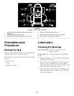
Page 28: ...e seat forward The following components can be accessed by raising the seat Service decal Fuses Battery and cables Lubrication Greasing the Bearings Service Interval Every 25 hours Grease all lubricat...

Page 29: ...en under dusty dirty conditions Every 50 hours Service the paper element more often under dusty dirty conditions Every 100 hours Yearly whichever comes first Replace the paper element more often under...

Page 30: ...emely dusty or dirty conditions Clean or replace the element as necessary Replace the air cleaner element yearly or every 100 hours 1 Open the air cleaner cover door on the blower housing to access th...

Page 31: ...down to the lowest point of the thread leads Do not screw the cap onto the tube Unthreaded dipstick caps reinsert the dipstick and push firmly into place 6 Remove the dipstick out and check the oil le...

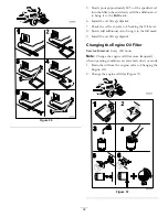
Page 32: ...to Checking the Oil Level 8 Slowly add additional oil to bring it to the full mark 9 Install the oil fill cap dipstick Changing the Engine Oil Filter Service Interval Every 200 hours Note Change the e...

Page 33: ...replace the spark plug s when it has a black coating worn electrodes an oily film or cracks If you see light brown or gray on the insulator the engine is operating properly A black coating on the insu...

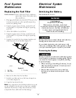
Page 34: ...ic ties the same as they were originally installed at the factory to keep the fuel line away from components that could cause fuel line damage Electrical System Maintenance Servicing the Battery Servi...

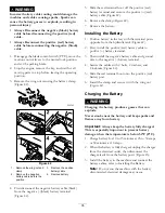
Page 35: ...Remove the clamp Figure 42 7 Remove the battery Installing the Battery 1 Position battery in the tray with the terminal posts opposite from the hydraulic tank Figure 42 2 First install the positive r...

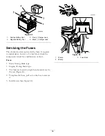
Page 36: ...maintenance however if a fuse blows check the component circuit for a malfunction or short Fuses Main 30 amp blade type Engine 20 amp blade type 1 The fuses are located on right hand console next to t...

Page 37: ...engine oil Important Use oil specified or equivalent Other fluids could cause system damage Checking the Hydraulic Oil Level Service Interval Every 25 hours Check expansion reservoir and if necessary...

Page 38: ...ter the first 50 hours Every 400 hours G008748 3 4 1 2 3 4 5 6 Figure 48 1 Apply a thin coat of oil on the surface of the rubber seal of each filter 2 Turn the filter clockwise until rubber seal conta...

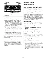
Page 39: ...the Cutting Blades Maintain sharp blades throughout the cutting season because sharp blades cut cleanly without tearing or shredding the grass blades Tearing and shredding turns grass brown at the edg...

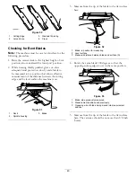
Page 40: ...edge and the level surface the machine is on G009679 1 2 3 Figure 51 1 Deck 3 Blade 2 Spindle housing 3 Measure from the tip of the blade to the flat surface here G009680 1 2 3 Figure 52 1 Blade in p...

Page 41: ...To ensure optimum performance and continued safety conformance of the machine use genuine Toro replacement blades Replacement blades made by other manufacturers may result in non conformance with safe...

Page 42: ...control switch 2 Move the motion control levers outward to the neutral lock position stop the engine remove the key and wait for all moving parts to stop before leaving the operating position 3 Caref...

Page 43: ...four leveling adjust locking nuts Figure 61 G010321 1 2 3 1 2 3 4 4 Figure 61 1 Deck lift arm 3 Leveling adjust locking nut 2 Deck hanger 4 Slot in deck hanger 5 Recheck that blocks fit just snugly u...

Page 44: ...ng parts to stop before leaving the operating position 3 Slide the mower under the machine 4 Lower the height of cut lever to the lowest position Place the height of cut pin in the lock position for l...

Page 45: ...efore the bend and going over the rod as it returns from the bend 4 Lift the long end of the spring and place it into the notch on the deflector assembly bracket Figure 65 G006049 1 2 3 4 Figure 65 1...

Page 46: ...he mower to the lowest height of cut 5 Sit on the seat and start the engine Engage the blade control switch and let the mower run for one to three minutes 6 Disengage the blade control switch stop the...

Page 47: ...wash the mower with a garden hose Note Run the machine with the blade control switch PTO engaged and the engine at high idle for 2 to 5 minutes after washing 11 Check the condition of the blades refe...

Page 48: ...eplace seat if needed 9 Electrical connections are corroded loose or faulty 9 Check the electrical connections for good contact Clean connector terminals thoroughly with electrical contact cleaner app...

Page 49: ...vice Dealer 6 Blade spindle is bent 6 Contact an Authorized Service Dealer Abnormal vibration 7 Motor mount is loose or worn 7 Contact an Authorized Service Dealer 1 Blade s not sharp 1 Sharpen the bl...

Page 50: ...Schematics G012083 Wire Diagram Rev B 50...

Page 51: ...Notes 51...

Page 52: ...Toro com You may also call the numbers listed in item 3 to use the 24 hour Toro Dealer locator system 2 Bring the product and your proof of purchase sales receipt to the Service Dealer The dealer wil...

Reviews: