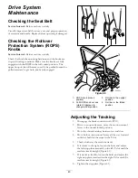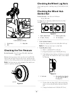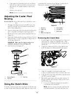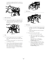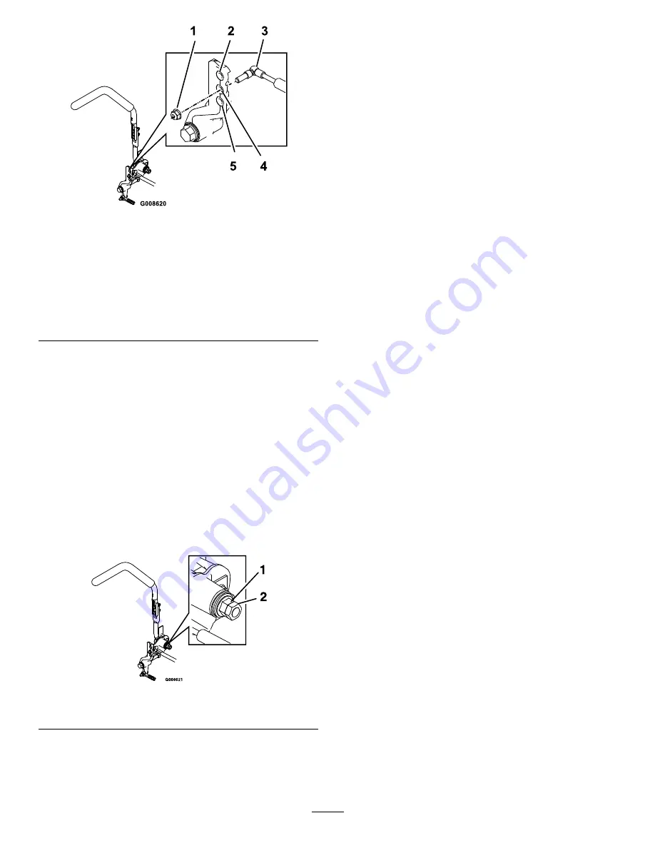
Figure 83
RH Motion Control Shown
1.
Torque the lock nut to 200 in-lb (16.7 ft-lb). Bolt must
protrude past end of locknut after torque.
2.
Least resistance (softest feel)
3.
Damper
4.
Medium resistance (medium feel)
5.
Most resistance (firmest feel)
Adjusting the Motion Control
Neutral Lock Pivot
The flanged nut can be adjusted to obtain a more desired
motion control lever resistance when moving it to the neutral
lock position. See Figure 84 for adjustment options.
1.
Loosen the jam nut.
2.
Tighten or loosen the flanged nut to the desired feel.
For more resistance, tighten the flanged nut.
For less resistance, loosen the flanged nut
3.
Tighten jam nut.
Figure 84
1.
Flanged nut
2.
Jam nut
Hydraulic System
Maintenance
Servicing the Hydraulic
System
Hydraulic Oil Type:
Toro
®
HYPR-OIL
™
500 hydraulic oil
or Mobil
®
1 15W-50.
Important:
Use oil specified. Other fluids could cause
system damage.
Each Hydraulic System Oil Capacity:
52 ounces (1.5 l) per
side with filter change
Checking the Hydraulic Oil
Service Interval:
Every 50 hours—Check the hydraulic oil
level.
1.
Position the machine on a level surface.
2.
Disengage the PTO, move the motion control levers to
the neutral locked position and set the parking brake.
3.
Stop the engine, remove the key, and wait for all moving
parts to stop before leaving the operating position.
4.
Allow the engine and hydraulic system to cool for ten
minutes.
Note:
The oil level on the dipstick will be incorrect
when the oil is checked and the unit is hot.
5.
Move the seat forward.
6.
Clean the area around the dipsticks of hydraulic system
reservoirs (Figure 85).
7.
Remove one dipstick from the hydraulic reservoir
(Figure 85).
8.
Wipe the dipstick off and thread the dipstick into the
reservoir.
9.
Remove the dipstick and look at the end (Figure 85).
If the oil level is at the add mark , slowly pour only
enough oil into the hydraulic reservoir to raise the level
to the full or
H
line.
Important:
Do not overfill the hydraulic units
with oil as damage may occur. Do not run the
machine with the oil below the add mark.
10.
Install the dipstick.
11.
Repeat procedure for the opposite dipstick.
53
Summary of Contents for 74901 Z Master 5000
Page 66: ...Schematics Wire Diagram Rev A 66 ...
Page 67: ...Notes 67 ...

