Product Overview
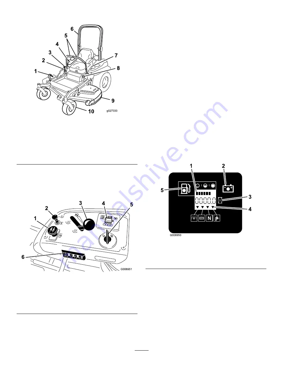
g027333
Figure 4
1.
Height-of-cut deck-lift
pedal
6.
Roll bar
2.
Transport lock
7.
Seat belt
3.
Parking brake lever
8.
Fuel cap
4.
Controls
9.
Mower deck
5.
Motion-control levers
10.
Caster wheel
Controls
Become familiar with all the controls before you start the
engine and operate the machine (
and
25
25
10
15
G008951
1
2
3
4
5
6
Figure 5
1.
PTO Switch
4.
Hour
meter/Safety-interlock
display
2.
Choke
5.
Ignition switch
3.
Throttle control
6.
Fuses
Hour Meter
The hour meter records the number of hours the engine has
operated. It operates when the engine is running. Use these
times for scheduling regular maintenance (
Fuel Gauge
The fuel gauge is located with the hour meter and the bars
light up when the ignition switch is on (
).
The indicator light appears when the fuel level is low
(approximately one gallon remaining in the fuel tank).
Safety-Interlock Indicators
There are symbols on the hour meter and the indicate with a
black triangle that the interlock component is in the correct
position (
Battery Indicator Light
If the ignition key is turned to the
On
position for a few
seconds, the battery voltage will be displayed in the area
where the hours are normally displayed.
The battery light turns on when the ignition is turned on and
when the charge is below the correct operating level (
).
Figure 6
1.
Fuel gauge (bars)
4.
Safety-interlock symbols
2.
Battery light
5.
Low fuel indicator light
3.
Hour meter
Throttle Control
The throttle control is variable between the
Fast
and
Slow
positions.
Blade-Control Switch (PTO)
The blade-control switch (PTO) is used to engage the electric
clutch and drive the mower blades. Pull the switch up to
engage the blades and release. To disengage the blades,
push the blade-control switch (PTO) down or move a
motion-control lever into the neutral lock position.
14
Summary of Contents for 74955
Page 65: ...Schematics G020788 Electrical Schematic Rev A 65 ...
Page 66: ...Notes 66 ...
Page 67: ...Notes 67 ...


