g295443
Figure 69
1.
Cam lock
3.
Lanyard
2.
Clevis pin
5.
Insert the height-of-cut pin into the 102 mm (4
inches) location and install the lanyard.
6.
Lock the each wing deck cam lock.
7.
Start the engine.
Note:
The parking brake must be engaged and
the motion-control levers must be out to start
the engine. The operator does not have to be in
the seat. Ensure that all persons are clear of
the deck wings.
8.
Press and hold the front of the deck-lift switch
until the center deck lowers and both wings are
completely unfolded to the cutting height.
9.
Shut off the engine, remove the key, and wait
for all moving parts to stop before leaving the
operating position.
10.
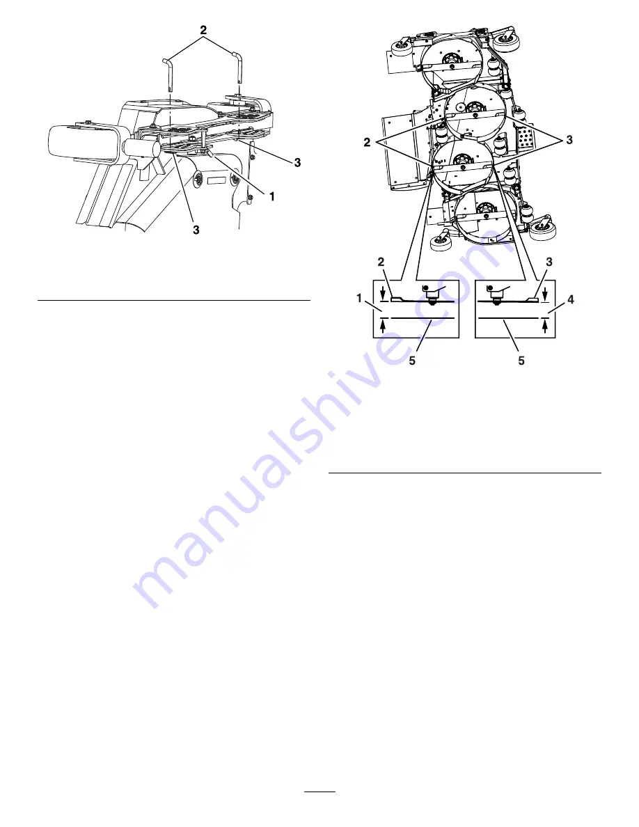
Measure from the level surface to the front tip of
the left and right center deck blades (
).
The measurement should read 102 mm (4
inches).
g295607
Figure 70
1.
108 mm (4-1/4 inches)
2.
Rear blade tip
3.
Front blade tip
4.
102 mm (4 inches)
5.
Level surface
Adjusting the Center Deck
1.
To increase the cutting height, turn the
adjuster screw clockwise; to decrease, turn it
counterclockwise.
Loosen the jam nuts on the top of each deck
adjuster. Fine-tune the adjuster on the front
deck-lift assembly by turning it to get the correct
height for the left and right, front blade tips on
the center deck (
).
2.
Measure the rear tip height.
Fine-tune the rear adjusters as required. You
can adjust the single-point adjustment to gain
more adjustment.
3.
Measure until all 4 sides are at the correct
height.
4.
Tighten all the jam nuts on the deck-lift arm
assemblies.
5.
If the 4 deck adjusters (
) do not have
enough adjustment to achieve the accurate
59
Summary of Contents for Air Cool Z Master 74090
Page 69: ...g008623 Hydraulic Schematic Rev A 69 ...
Page 72: ......

