g006530
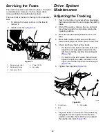
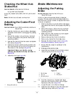
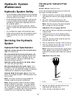
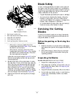
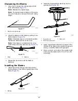
Figure 74
1.
Cutting edge
3.
Wear/slot forming
2.
Curved area
4.
Crack
Checking for Bent Blades
1.
Disengage the blade-control switch (PTO), move
the motion-control levers to the N
EUTRAL
-
LOCK
position, and engage the parking brake.
2.
Shut off the engine, remove the key, and wait
for all moving parts to stop before leaving the
operating position.
3.
Rotate the blades until the ends face forward
and backward (
4.
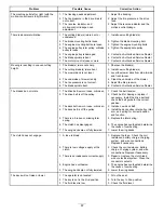
Measure from a level surface to the cutting
edge, position
A
, of the blades (
g243961
Figure 75
1.
Position A
2.
Measure here from the
blade to a hard surface.
5.
Rotate the opposite ends of the blades forward.
6.
Measure from a level surface to the cutting edge
of the blades at the same position as in step
.
Note:
The difference between the dimensions
obtained in steps
and
must not exceed 3
mm (1/8 inch).
Note:
If this dimension exceeds 3 mm (1/8
inch), the blade is bent and must be replaced.
DANGER
A blade that is bent or damaged could
break apart and could seriously injure or
kill you or bystanders.
•
Always replace bent or damaged
blade with a new blade.
•
Never file or create sharp notches in
the edges or surfaces of blade.
Removing the Blades
Replace the blades if they hit a solid object, or if the
blade is out of balance or bent.
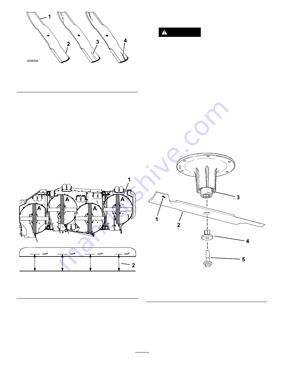
1.
Place a wrench on the flat of the spindle shaft or
hold the blade end using a rag or thickly padded
glove.
2.
Remove the blade bolt, bushing, and blade from
the spindle shaft (
).
g295816
Figure 76
1.
Sail area of the blade
4.
Bushing
2.
Blade
5.
Blade bolt
3.
Flat of the spindle shaft
62
Summary of Contents for Air Cool Z Master 74090
Page 69: ...g008623 Hydraulic Schematic Rev A 69 ...
Page 72: ......


