background image

Safety

This machine has been designed in accordance with
ANSI standard B71.4-2017.

Safety Alert Symbol

This Safety Alert Symbol (

Figure 2

) is used both in

this manual and on the machine to identify important
safety messages which must be followed to avoid
accidents.

This symbol means:

ATTENTION! BECOME ALERT!

YOUR SAFETY IS INVOLVED!

g000502

Figure 2

Safety Alert Symbol

The safety alert symbol appears above information
which alerts you to unsafe actions or situations and
will be followed by the word

DANGER

,

WARNING

, or

CAUTION

.

DANGER

: Indicates an imminently hazardous

situation which, if not avoided,

Will

result in death or

serious injury.

WARNING

: Indicates a potentially hazardous situation

which, if not avoided,

Could

result in death or serious

injury.

CAUTION

: Indicates a potentially hazardous situation

which, if not avoided,

May

result in minor or moderate

injury.

This manual uses two other words to highlight
information.

Important

calls attention to special

mechanical information and

Note

emphasizes general

information worthy of special attention.

General Safety

This machine is capable of amputating hands and feet
and of throwing objects. Toro designed and tested
this lawn mower to offer reasonably safe service;
however, failure to comply with safety instructions
may result in injury or death.

Read, understand, and follow all instructions and
warnings in the Operator’s Manual and other
training material, on the machine, engine, and
attachments. All operators and mechanics should
be trained. If the operator(s) or mechanic(s) can
not read this manual, it is the owner’s responsibility
to explain this material to them; other languages
may be available on our website.

Only allow trained, responsible, and physically
capable operators that are familiar with the safe
operation, operator controls, and safety signs and
instructions to operate the machine. Never let
children or untrained people operate or service the
equipment. Local regulations may restrict the age
of the operator.

Always keep the roll bar in the fully raised and
locked position and use the seat belt.

Do not operate the machine near drop-offs,
ditches, embankments, water, or other hazards, or
on slopes greater than 15 degrees.

Do not put your hands or feet near moving
components of the machine.

Never operate the machine with damaged guards,
shields, or covers. Always have safety shields,
guards, switches and other devices in place and in
proper working condition.

Stop the machine, shut off the engine, and remove
the key before servicing, fueling, or unclogging
the machine.

5


Summary of Contents for Air Cool Z Master 74090

Page 1: ...Form No 3435 701 Rev B 96in Air Cool Z Master Professional Riding Mower Model No 74090 Serial No 400000000 and Up Register at www Toro com Original Instructions EN 3435 701 B ...

Page 2: ...lies with all relevant European directives for details please see the separate product specific Declaration of Conformity DOC sheet The gross or net torque of this engine was laboratory rated by the engine manufacturer in accordance with the Society of Automotive Engineers SAE J1940 or J2723 As configured to meet safety emission and operating requirements the actual engine torque on this class of ...

Page 3: ...cessory information help finding a dealer or to register your product Whenever you need service genuine Toro parts or additional information contact an Authorized Service Dealer or Toro Customer Service and have the model and serial numbers of your product ready Figure 1 identifies the location of the model and serial numbers on the product Write the numbers in the space provided Important With yo...

Page 4: ...ng the Caster Wheel Hubs 38 Engine Maintenance 39 Engine Safety 39 Servicing the Air Cleaner 39 Servicing the Engine Oil 41 Servicing the Spark Plug 43 Checking the Spark Arrester 44 Fuel System Maintenance 45 Replacing the Fuel Filter 45 Servicing the Fuel Tank 46 Inspecting the Engine Valve Clearance 46 Checking the Fuel Lines and Connections 46 Electrical System Maintenance 46 Electrical System...

Page 5: ...sted this lawn mower to offer reasonably safe service however failure to comply with safety instructions may result in injury or death Read understand and follow all instructions and warnings in the Operator s Manual and other training material on the machine engine and attachments All operators and mechanics should be trained If the operator s or mechanic s can not read this manual it is the owne...

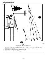
Page 6: ...rees Use the slope chart to determine the degree of slope of hills before operating Do not operate this machine on a slope greater than 15 degrees Fold along the appropriate line to match the recommended slope 2 Align this edge with a vertical surface a tree building fence pole etc 3 Example of how to compare slope with folded edge 6 ...

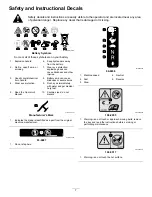
Page 7: ...chemical burn hazard 8 Battery acid can cause blindness or severe burns 4 Wear eye protection 9 Flush eyes immediately with water and get medical help fast 5 Read the Operator s Manual 10 Contains lead do not discard decaloemmarkt Manufacturer s Mark 1 Indicates the blade is identified as a part from the original machine manufacturer decal93 6687 93 6687 1 Do not step here decal99 8936 99 8936 1 M...

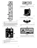
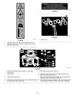
Page 8: ...al109 6036 109 6036 Rear Discharge Machines Only 1 Read the Operator s Manual 2 Remove the key and read the instructions before servicing or performing maintenance 3 Height of cut decal112 9028 112 9028 1 Warning stay away from moving parts keep all guards and shields in place decal116 5988 116 5988 1 Parking brake engaged 2 Parking brake disengaged decal116 8726 116 8726 1 Read the Operator s Man...

Page 9: ... Check the tire pressure 2 locations 2 Time interval 6 Grease the idler pivots refer to the Operator s Manual for further instructions 4 locations 3 Check the engine oil level 7 Grease the front caster wheel bearings refer to the Operator s Manual for further instructions 4 locations 4 Check the hydraulic fluid level refer to the Operator s Manual for further instructions 3 locations 8 Grease the ...

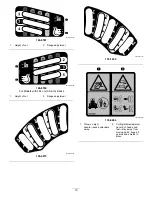
Page 10: ...s with 244 cm 96 inch Decks 1 Height of cut 2 Range adjustment decal126 9275 126 9275 decal135 1432 135 1432 decal135 0664 135 0664 1 Thrown object hazard keep bystanders away 2 Cutting dismemberment hazard of hands and feet stay away from moving parts keep all guards and shields in place 10 ...

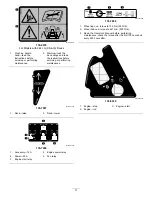
Page 11: ...35 7057 135 7057 1 Deck raise 2 Deck lower decal135 7226 135 7226 1 Accessory 15 A 4 Engine power relay 2 Power 20 A 5 Fan relay 3 Engine start relay decal135 7898 135 7898 1 Wheel lug nut torque to 129 N m 95 ft lb 2 Wheel hub nut torque to 441 N m 325 ft lb 3 Read the Operator s Manual before performing maintenance check the torque after the first 100 hours and every 500 hours after decal136 553...

Page 12: ...ration for the machine 1 Warning read the Operator s Manual all operators should be trained before operating the machine wear hearing protection 4 Tipping hazard do not use dual ramps when loading onto a trailer use 1 ramp wide enough for the machine use a ramp with a slope less than 15 back up the ramp in reverse and drive forward off the ramp 2 Cutting dismemberment hazard of hand stay away from...

Page 13: ...splay monitor 4 Fuel tank cap 7 Wing deck caster wheel 10 Anti scalp roller 2 Motion control lever 5 Parking brake lever 8 Caster wheel 11 Center deck height of cut pin 3 Roll bar 6 Wing deck height of cut pin 9 Center deck 12 Wing deck 13 ...

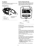
Page 14: ...s information relative to machine operation refer to the Software Guide for more information Buttons The multi functional buttons are located at the bottom of the panel The icons displayed on the information screen above the buttons indicate the current function The buttons allow you to select the engine speed and navigate through system menus Refer to the Software Guide for more information LED S...

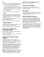
Page 15: ...en the PTO switch is disengaged Note Machines equipped with the Horizon Display Monitor have a clutch saver which allows the throttle to automatically reduce the engine speed when you disengage the PTO switch Engaging and disengaging the PTO switch changes the engine throttle between MOW and TRANSPORT mode Note The system allows you to start the machine with the PTO switch engaged but does not eng...

Page 16: ...the operation of the machine and may cause personal injury to the operator or bystanders Wear appropriate personal protective equipment such as safety glasses substantial slip resistant footwear and hearing protection Tie back long hair and avoid loose clothing and loose jewelry which may get tangled in moving parts CAUTION This machine produces sound levels in excess of 85 dBA at the operator s e...

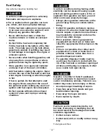
Page 17: ...electricity can be released causing a spark which can ignite gasoline vapors A fire or explosion from gasoline can burn you and others and cause property damage Always place gasoline containers on the ground away from your vehicle before filling Do Not fill gasoline containers inside a vehicle or on a truck or trailer bed because interior carpets or plastic truck bed liners may insulate the contai...

Page 18: ...ning methanol Do not store fuel either in the fuel tank or fuel containers over the winter unless you use a fuel stabilizer Do not add oil to gasoline Using Stabilizer Conditioner Use a fuel stabilizer conditioner in the machine to provide the following benefits Keeps fuel fresh longer when used as directed by the fuel stabilizer manufacturer Cleans the engine while it runs Eliminates gum like var...

Page 19: ... Important Lower the roll bar only when absolutely necessary 1 Ensure that the knob is completely latched with the tabs interlocking as shown in Figure 8 to lock the roll bar in the raised position 2 To lower the roll bar apply forward pressure to the upper part of the roll bar 3 Pull both knobs out and rotate them 90 so they are not engaged Figure 8 4 To raise the roll bar raise the roll bar to t...

Page 20: ...you use the machine each time If the safety system does not operate as described below have an Authorized Service Dealer repair the safety system immediately 1 Sit on the seat engage the parking brake and move the blade control switch PTO to the ON position Try starting the engine the engine should not start 2 Sit on the seat engage the parking brake and move the blade control switch PTO to the OF...

Page 21: ... to unlock the seat Figure 11 g019754 Figure 11 Unlatching the Seat g019755 Figure 12 1 Seat latch 2 Seat Changing the Seat Suspension The seat is adjustable to provide a smooth and comfortable ride Position the seat where you are most comfortable To adjust it turn the knob in front either direction to provide the best comfort Figure 13 g019768 Figure 13 1 Seat suspension knob 21 ...

Page 22: ...Be sure all drives are in neutral and parking brake is engaged before starting engine Use seat belts with the roll bar in the raised and locked position Start the engine carefully according to instructions with feet well away from the blades Never operate the mower with damaged guards shields or covers Always have safety shields guards switches and other devices in place and in proper working cond...

Page 23: ...e common sense and good judgment when performing this evaluation Changes in the terrain such as moisture can quickly affect the operation of the machine on a slope Identify hazards at the base of the slope Do Not operate the machine near drop offs ditches embankments water or other hazards The machine could suddenly roll over if a wheel goes over the edge or the edge collapses Keep a safe distance...

Page 24: ...ll bar as soon as clearance permits Be certain that the seat belt can be released quickly in the event of an emergency Check carefully for overhead clearances i e branches doorways and electrical wires before driving under any objects and Do Not contact them In the event of a rollover take the unit to an Authorized Service Dealer to have the ROPS inspected Replace a damaged ROPS Do Not repair or r...

Page 25: ... clear of the deck wings 3 Press and hold the bottom of the deck lift switch the wing decks lower first then the center deck Operating the Mower Blade Control Switch PTO The blade control switch PTO starts and stops the mower blades and any powered attachments Engaging the Blade Control Switch PTO Note Engaging the blade control switch PTO with the throttle position at half or less causes excessiv...

Page 26: ...t the starter motor Note You may need multiple attempts to start the engine the first time after adding fuel to an empty fuel system g230704 Figure 20 Shutting Off the Engine CAUTION Children or bystanders may be injured if they move or attempt to operate the machine while it is unattended Always remove the key and engage the parking brake when leaving the machine unattended g230715 Figure 21 26 ...

Page 27: ...gage the parking brake 4 Shut off the engine remove the key and wait for all moving parts to stop before leaving the operating position 5 Remove the clevis pin and hairpin cotter from the storage location and secure each wing in the upright position Figure 22 g212236 Figure 22 1 Clevis pin 2 Hairpin cotter Using the Motion Control Levers g004532 Figure 23 1 Motion control lever NEUTRAL LOCK positi...

Page 28: ...e can spin very rapidly You may lose control of the machine and cause personal injury or damage to the machine Use caution when making turns Slow the machine down before making sharp turns Driving Forward Note The engine shuts off when you move the traction control with the parking brake engaged To stop the machine pull the motion control levers to the NEUTRAL position 1 Disengage the parking brak...

Page 29: ... place B Unlock the cam locks located on the height of cut channel on the wing deck Figure 26 g295443 Figure 26 1 Cam lock 3 Lynch pin 2 Height of cut pin C Remove the lynch pin from the height of cut pin on both the front and rear channels D Move the wing deck to the appropriate height and install the height of cut pins and lynch pins Figure 26 E Lock the cam lock F Repeat for the other wing deck...

Page 30: ...ust the anti scalp rollers by removing the mounting hardware 5 Place the rollers in 1 of the positions shown in Figure 28 The rollers will maintain 19 mm 3 4 inch clearance to the ground to minimize gouging and roller wear or damage g243016 Figure 28 For cutting heights above 90 mm 3 1 5 inches use the bottom hole The rollers are still effective against scalping 1 Anti scalp roller mounting bracke...

Page 31: ... the same cutting height mow more often in early spring As the grass growth rate slows in mid summer mow less frequently If you cannot mow for an extended period first mow at a high cutting height then mow again 2 days later at a lower height setting Using a Slower Cutting Speed To improve cut quality use a slower ground speed in certain conditions Avoiding Cutting Too Low When mowing uneven turf ...

Page 32: ...re accessing the drive wheel release valves WARNING The engine and hydraulic drive units can become very hot Touching a hot engine or hydraulic drive units can cause severe burns Allow the engine and hydraulic drive units to cool completely before accessing the drive wheel release valves The drive wheel release valves are located in the back of each hydraulic drive unit under the seat Note Make su...

Page 33: ...l ramps for each side of the machine Do not exceed a 15 degree angle between the ramp and the ground or between the ramp and the trailer or truck Ensure that the length of the ramp is at least 4 times as long as the height of the trailer or truck bed to the ground This ensures that the ramp angle does not exceed 15 degrees on flat ground g027996 Figure 32 1 Full width ramp in stowed position 4 Ram...

Page 34: ... machine up the ramp 2 Drive the machine forward down the ramp 5 Shut off the engine remove the key and engage the parking brake 6 Tie down the machine near the front caster wheels and the rear bumper with straps chains cable or ropes Figure 34 Refer to local regulations for tie down requirements g292532 Figure 34 1 Tie down loops Unloading the Machine 1 Lower the ramp ensuring that the angle betw...

Page 35: ...ories may alter the warranty controllability and safety of the machine Unauthorized modifications to the original equipment or failure to use original Toro parts could lead to serious injury or death Unauthorized changes to the machine engine fuel or venting system may violate applicable safety standards such as ANSI OSHA and NFPA and or government regulations such as EPA and CARB WARNING Hydrauli...

Page 36: ... After the first 5 hours Change the engine oil After the first 100 hours Check the wheel lug nuts Check the wheel hub slotted nut torque specifications Adjust the parking brake After the first 250 hours Change the hydraulic filter and fluid Before each use or daily Check the safety system Check the air cleaner for dirty loose or damaged parts Check the engine oil level Inspect the blades Clean the...

Page 37: ...accidently start the engine and seriously injure you or other bystanders Shut off the engine and remove the key from the switch before you perform any maintenance Lubrication Greasing the Machine Grease more frequently when operating conditions are extremely dusty or sandy Grease Type No 2 lithium or molybdenum grease 1 Park the machine on a level surface disengage the blade control switch and eng...

Page 38: ...pivots Note Keep the dust cap off until greasing is done 6 Remove the hex plug 7 Thread a grease fitting into the hole 8 Pump grease into the fitting until it oozes out around the top bearing 9 Remove the grease fitting in the hole 10 Install the hex plug and dust cap Figure 38 g009187 Figure 38 11 Grease the caster wheel bearings Figure 38 Lubricating the Caster Wheel Hubs Service Interval Yearly...

Page 39: ...re that the axle does not extend beyond either nut 17 Install the seal guards over the wheel hub and insert the wheel into the caster fork 18 Install the caster bolt and tighten the nut fully Important To prevent seal and bearing damage check the bearing adjustment often Spin the caster tire The tire should not spin freely more than 1 or 2 revolutions or have any side play If the wheel spins freel...

Page 40: ...aner body 3 Air cleaner cover 10 Inspect the primary filter for damage by looking into the filter while shining a bright light on the outside of the filter Note Holes in the filter will appear as bright spots If the filter is damaged discard it Servicing the Foam Element 1 Wash the foam element in liquid soap and warm water When the element is clean rinse it thoroughly 2 Dry the element by squeezi...

Page 41: ...ty conditions Every 200 hours Change the engine oil filter more often in dirty or dusty conditions Engine Oil Specifications Oil Type Detergent oil API service SJ or higher Oil Capacity 1 8 L 61 fl oz with a filter change 1 6 L 54 fl oz without a filter change Viscosity See the table below g017552 Figure 42 Checking the Engine Oil Level Note Check the oil when the engine is cold Important If you o...

Page 42: ...pletely 3 Disengage the blade control switch PTO and engage the parking brake 4 Shut off the engine remove the key and wait for all moving parts to stop before leaving the operating position 5 Drain the oil from the engine Figure 44 g027734 Figure 44 6 Slowly pour approximately 80 of the specified oil into the filler tube and slowly add the additional oil to bring it to the Full mark Figure 45 g19...

Page 43: ...YC Air Gap 0 76 mm 0 03 inch Removing the Spark Plug 1 Park the machine on a level surface disengage the blade control switch PTO and engage the parking brake 2 Shut off the engine remove the key and wait for all moving parts to stop before leaving the operating position 3 Clean the area around the base of the plug s to keep dirt and debris out of the engine 4 Locate and remove the spark plug s as...

Page 44: ...uel or run the engine unless the spark arrester is installed 1 Park the machine on a level surface disengage the PTO and engage the parking brake 2 Shut off the engine remove the key and wait for all moving parts to stop before leaving the operating position 3 Wait for the muffler to cool 4 If you see any breaks in the screen or welds replace the arrester 5 If the screen is plugged remove the arre...

Page 45: ...ies the same as they were originally installed at the factory to keep the fuel line away from components that can cause fuel line damage 1 Park the machine on a level surface disengage the blade control switch PTO and engage the parking brake 2 Shut off the engine remove the key and wait for all moving parts to stop before leaving the operating position 3 Allow the machine to cool down 4 Close the...

Page 46: ...ectrolyte contains sulfuric acid which is fatal if consumed and causes severe burns Do not drink electrolyte and avoid contact with skin eyes or clothing Wear safety glasses to shield your eyes and rubber gloves to protect your hands Checking the Battery Charge Service Interval Monthly Allowing the battery to stand for an extended period of time without charging it results in reduced performance a...

Page 47: ...Important Always keep the battery fully charged 1 265 specific gravity This is especially important to prevent battery damage when the temperature is below 0 C 32 F 1 Make sure that the filler caps are installed in battery Charge battery for 10 to 15 minutes at 25 to 30 A or 30 minutes at 10 A 2 When the battery is fully charged unplug the charger from the electrical outlet then disconnect the cha...

Page 48: ... batteries Note The following instructions are adapted from the SAE J1494 Rev Dec 2001 Battery Booster Cables Surface Vehicle Recommended Practice SAE Society of Automotive Engineers Important Ensure that the vent caps are tight and level Place a damp cloth if available over any vent caps on both batteries Ensure that the machines do not touch and that both electrical systems are shut off and at t...

Page 49: ... for all moving parts to stop before leaving the operating position 3 Move the throttle midway between FAST and Slow 4 Move both motion control levers all the way forward until they both hit the stops in the T slot 5 Check which way the machine tracks If it tracks to the right loosen the bolts and adjust the left stop plate rearward on the left T slot until the machine tracks straight Figure 54 If...

Page 50: ...re maintenance DANGER Low tire pressure decreases machine side hill stability This could cause a rollover which may result in personal injury or death Do not under inflate the tires Check the air pressure in the rear tires Add or remove air as needed to set the air pressure in the tires to the tire air pressure specification Important Maintain pressure in all tires to ensure a good quality of cut ...

Page 51: ... 100 hours Every 500 hours Check to ensure that parking brake is adjusted properly This procedure must be followed after the first 100 hours or when a brake component has been removed or replaced 1 Park the machine on a level surface disengage the blade control switch and engage the parking brake 2 Shut off the engine remove the key and wait for all moving parts to stop before leaving the operatin...

Page 52: ...Deck Belts Squealing when the belt is rotating blades slipping when cutting grass frayed belt edges burn marks and cracks are signs of a worn mower belt Replace the belt if any of these conditions are evident 1 Park the machine on a level surface disengage the blade control switch and engage the parking brake 2 Shut off the engine remove the key and wait for all moving parts to stop before leaving...

Page 53: ... switch and engage the parking brake 2 Shut off the engine remove the key and wait for all moving parts to stop before leaving the operating position 3 Lower the mower to the 76 mm 3 inches height of cut 4 Remove the 2 wing deck belts refer to Replacing the Wing Deck Belts page 52 5 Use a ratchet in the square hole in the idler arm to remove tension on the idler spring Figure 62 6 Remove the belt ...

Page 54: ...either side of the machine below the seat are the pump control linkages Rotating the end nut with a 1 2 inch deep socket wrench allows fine tuning adjustments so that the machine does not move in neutral Any adjustments should be made for neutral positioning only WARNING The engine must be running and the drive wheels turning so that you can perform the adjustments Contact with moving parts or hot...

Page 55: ...direction until the wheels slightly creep in reverse Figure 65 g299537 Figure 65 1 Double nuts 11 Move the motion control levers to the REVERSE position and while applying slight pressure to the lever allow the reverse indicator springs to bring the levers back to neutral Note The wheels should stop turning or slightly creep in reverse 12 Shut off the machine 13 Remove the jumper wire from the wir...

Page 56: ...Note Toro does not assume responsibility for damage caused by improper substitutions Note Many hydraulic fluids are almost colorless making it difficult to spot leaks A red dye additive for the hydraulic system fluid is available in 20 ml 2 3 fl oz bottles 1 bottle is sufficient for 15 to 22 L 4 to 6 gallons of hydraulic fluid Order Part Number 44 2500 from your authorized Toro distributor Checkin...

Page 57: ...st 250 hours Every 500 hours thereafter Mobil 1 15W50 After first 250 hours Every 250 hours thereafter May need more often under severe conditions 11 Remove the drain pan and properly dispose of the hydraulic fluid and filter according to local codes 12 Install the pump drive belt 13 Start engine and move throttle control to the FAST position 14 Move the motion control levers to full speed and run...

Page 58: ...k Maintenance Leveling the Mower Deck Setting up the Machine Note Ensure that the mower deck is level before matching the height of cut HOC 1 Park the machine on a level surface disengage the blade control switch and engage the parking brake 2 Shut off the engine remove the key and wait for all moving parts to stop before leaving the operating position 3 Check tire pressure of the drive tires If n...

Page 59: ...ip of the left and right center deck blades Figure 70 The measurement should read 102 mm 4 inches g295607 Figure 70 1 108 mm 4 1 4 inches 2 Rear blade tip 3 Front blade tip 4 102 mm 4 inches 5 Level surface Adjusting the Center Deck 1 To increase the cutting height turn the adjuster screw clockwise to decrease turn it counterclockwise Loosen the jam nuts on the top of each deck adjuster Fine tune ...

Page 60: ... least 1 3 the length of the available travel in their slots This will attain some up and down adjustment on each of the 4 deck links g232012 Figure 72 1 Single point height adjustment bolt 2 Front height of cut plate mounting bolt 3 Rear height of cut plate mounting bolt 8 Torque the front and rear height of cut plate mounting bolts to 37 to 45 N m 27 to 33 ft lb Adjusting the Wing Decks 1 Measur...

Page 61: ... the blade could be thrown toward you or bystanders resulting in serious personal injury or death Trying to repair a damaged blade may result in discontinued safety certification of the product Inspect the blades periodically for wear or damage Use care when checking the blades Wrap the blades or wear gloves and use caution when servicing the blades Only replace or sharpen the blades never straigh...

Page 62: ...tting edge of the blades at the same position as in step 4 Note The difference between the dimensions obtained in steps 4 and 5 must not exceed 3 mm 1 8 inch Note If this dimension exceeds 3 mm 1 8 inch the blade is bent and must be replaced DANGER A blade that is bent or damaged could break apart and could seriously injure or kill you or bystanders Always replace bent or damaged blade with a new ...

Page 63: ...l off the end of the sail area only Figure 77 g000277 Figure 78 1 Blade 2 Balancer 3 Repeat this procedure until the blade is balanced Installing the Blades 1 Install the bushing through the blade with the bushing flange on the bottom grass side of the blade Figure 79 g255205 Figure 79 1 Bushing 2 Install the bushing blade assembly into the spindle shaft Figure 80 g298850 Figure 80 1 Top spindle n...

Page 64: ... deflector Cleaning the Hydro Fan Cooling Guards Hydro Cooling Fins and Fan Service Interval Before each use or daily Remove the debris from the hydro fan cooling guards hydro cooling fins and fan to allow the hydro system to run cooler and improve the life of the hydro system 1 Park the machine on a level surface disengage the blade control switch and engage the parking brake 2 Shut off the engin...

Page 65: ...ge 50 8 Change the hydraulic fluid and filter refer to Changing the Hydraulic Fluid and Filter page 57 9 Charge the battery refer to Charging the Battery page 47 10 Scrape any heavy buildup of grass and dirt from the underside of the mower then wash the mower with a garden hose Note Run the machine with the blade control switch PTO engaged and the engine at high idle for 2 to 5 minutes after washi...

Page 66: ...the electrical connections for good contact Clean the connector terminals thoroughly with electrical contact cleaner apply dielectric grease and connect The engine does not start starts hard or fails to keep running 9 The relay or switch is broken 9 Contact an Authorized Service Dealer 1 The engine load is excessive 1 Reduce the ground speed 2 The air cleaner is dirty 2 Clean the air cleaner eleme...

Page 67: ...ing height 6 The blade spindle bent 6 Contact an Authorized Service Dealer 1 The drive belt is worn loose or broken 1 Check the belt tension 2 The drive belt is off the pulley 2 Check belt for damage replace if necessary Install the drive belt and check the belt guide for the correct position 3 The deck belt is worn loose or broken 3 Install a new deck belt 4 The deck belt is off the pulley 4 Inst...

Page 68: ...CK BLACK BLACK PWM E A D D OIL COOLER FAN M01 M SP07 SP01 SP02 SP03 SP04 SP05 SP06 SP08 CAP01 DUST CAP SP10 SP11 BLACK GREEN WHITE GREEN WHITE RED BLACK BLACK D01 DIODE BLACK RED GREEN RED GREEN BLACK R01 30K OHM FAN K07 30 85 86 87 ORANGE ORANGE ATC ATO FUSE HOLDER CAP F03 40A FAN FUSE SW05 DOWN ON OFF ON UP D02 DIODE ORANGE ORANGE ORANGE ORANGE BLACK D03 DIODE SP13 ORANGE WHITE ORANGE WHITE ORAN...

Page 69: ...g008623 Hydraulic Schematic Rev A 69 ...

Page 70: ...V 0 022 IN3 REV 221 BAR 7 3200 PSI 100 OR2 020 OR1 020 PORTS A B C 7 16 20 UNF 4 SAE FOLD CYLINDERS DECK LIFT CYLINDER 2 3 4 1 RATIO 1 A B C 345 BAR 7 5000 PSI 100 g299104 Wing Deck Lift Hydraulic Diagram Rev A 70 ...

Page 71: ...to restaurants grocery stores hotels schools and hospitals and on a wide variety of products Additionally some online and mail order retailers provide Prop 65 warnings on their websites or in catalogs How do the California warnings compare to federal limits Prop 65 standards are often more stringent than federal and international standards There are various substances that require a Prop 65 warnin...

Page 72: ......
Reviews: