GB–8
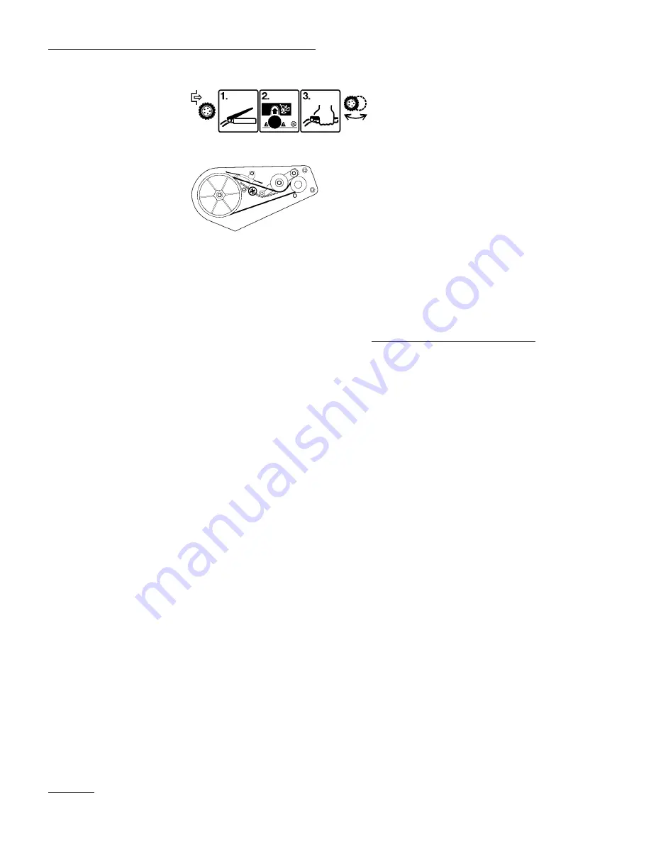
PowerShift operation
Belt routing
Assembly
Note:
Determine left and right sides of
snowthrower by standing in the normal
operating position.
Note:
Figures referenced in this section are
contained in the front of this
document.
Install Discharge Chute (Fig. 2)
1.
Position holes on sides of discharge chute over
hex bolts on sides of chute handle. Secure
discharge chute onto hex bolts with (2) washers
and (2) locknuts. While holding hex bolt heads
with a wrench (7/16), tighten locknuts securely.
2.
Rotate discharge chute to the completely upright
position. Secure rear of discharge chute with a
washer and locknut.
Install Handle (Fig. 3)
1.
Position ends of upper handle on inside of lower
handles and align holes. Ensure that the handle is
positioned so that the control bar is on the upper
side of the handle.
2.
Secure upper handle to lower handles using oval
head bolts, curved washers, and knobs. Position
knobs and curved washers on inside of handle
and TIGHTEN KNOBS SECURELY to
prevent them from loosening.
Note:
Make sure the oval head bolts and
curved washers are aligned correctly as
shown in Figure 3 to prevent knobs
from loosening.
Install Control Cable
1.
Route control cable through loop on left side of
snowthrower.
2.
Hook spring to round hole at end of cable
adjuster (Fig. 4).
3.
Route cable through elongated hole in cable
adjuster. Insert Z fitting on end of cable into 3rd
hole on cable adjuster (Fig. 4).
4.
Slide spring cover over spring and cable adjuster.
Push spring end through hole at end of spring
cover (Fig. 5).
5.
Hook spring into top hole of control bar bracket
(Fig. 5).
6.
Move control bar back toward handle until slack
in cable is removed. The gap between the control
bar bracket and handle should be approximately


