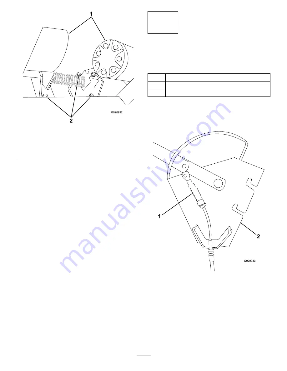
g020932
Figure 9
1.
Rear wheel motors
2.
Bolts (5/16 x 1 inch)
and locknuts (5/16
inch)—fourth bolt and
locknut not visible
4.
Secure the brake assembly to the frame with the
4 bolts (5/16 x 1 inch) and 4 locknuts (5/16 inch)
as shown in
.
Note:
You must push the bolts through the
frame and the brake cable brackets from the
rear of the machine.
5
Installing the Parking-Brake
Lever
Parts needed for this procedure:
1
Parking-brake lever assembly
1
Clevis pin (3/4 inch)
1
Cotter pin (3/4 inch)
Procedure
1.
Route the cable across the parking-brake lever
assembly (
).
g020933
Figure 10
1.
Parking-brake cable
2.
Parking-brake lever
assembly
2.
Secure the cable to the lever with the clevis pin
(3/4 inch) and the cotter pin (3/4 inch) as shown
in
5
Summary of Contents for Dingo 22366
Page 11: ...Notes...
Page 12: ......


