ENGINE
4-85
TX525 Service Manual
Rev. 000
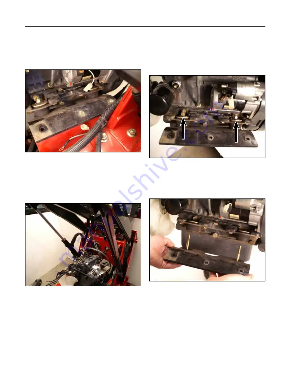
91. Using a 9/16” socket and wrench, remove the
remaining 2 bolts and nuts securing the left hand
side of the engine assembly to the mainframe (Fig.
0394).
Fig 0394
PICT-5484
92. Position and center an engine hoist over the engine.
Attach chain hooks into the engine lift brackets (Fig.
0395).
Fig 0395
PICT-5485
93. Lift engine out of the frame.
94. Using a 9/16” socket and wrench, remove the 2
screws securing the engine mount plate to the left
hand engine mount (Fig. 0396).
Fig 0396
PICT-5487
95. Remove the engine mount plate (Fig. 0397).
Fig 0397
PICT-5488
Summary of Contents for Dingo TX 525
Page 1: ...TX525 Service Manual Sitework Systems Form No 492 9195...
Page 3: ...ii Rev 000 TX525 Service Manual 8 01 10 Revision 000 REVISIONS...
Page 11: ...x Rev 000 TX525 Service Manual TABLE OF CONTENTS THIS PAGE INTENTIONALLY LEFT BLANK...
Page 243: ...ENGINE 4 190 Rev 000 TX525 Service Manual THIS PAGE INTENTIONALLY LEFT BLANK...
Page 263: ...ELECTRICAL 5 20 Rev 000 TX525 Service Manual THIS PAGE INTENTIONALLY LEFT BLANK...
Page 377: ...HYDRAULIC SYSTEM 6 114 Rev 000 TX525 Service Manual THIS PAGE INTENTIONALLY LEFT BLANK...
Page 479: ...DRIVE SYSTEM 7 102 Rev 000 TX525 Service Manual THIS PAGE INTENTIONALLY LEFT BLANK...
Page 553: ...HYDRAULIC TESTING 9 20 Rev 000 TX525 Service Manual THIS PAGE INTENTIONALLY LEFT BLANK...


