HYDRAULIC SYSTEM
6-20
Rev. 000
TX525 Service Manual
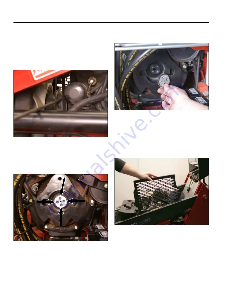
4. Remove the 4 bolts securing the hub sleeve to the
flywheel (Fig. 0905).
Fig 0905
PICT-4863
5. Remove the hub sleeve (Fig. 0906).
Fig 0906
PICT-4828a
Coupling Installation
1. Raise the hood and remove the left side grill (Fig.
0907).
Fig 0907
PICT-6962a
3. Secure the flywheel to keep it from turning. You
can do this by sliding a length of 5/16” diameter rod
stock in between the fan mount pulley and fan mount
spacer. The rod stock should be inserted so it runs
on top of the fan mount pulley screw. The rod stock
should be at least 16” long so that it rests on the left
hand loader arm lift cylinder (Fig. 0904).
Fig 0904
PICT-4840
Summary of Contents for Dingo TX 525
Page 1: ...TX525 Service Manual Sitework Systems Form No 492 9195...
Page 3: ...ii Rev 000 TX525 Service Manual 8 01 10 Revision 000 REVISIONS...
Page 11: ...x Rev 000 TX525 Service Manual TABLE OF CONTENTS THIS PAGE INTENTIONALLY LEFT BLANK...
Page 243: ...ENGINE 4 190 Rev 000 TX525 Service Manual THIS PAGE INTENTIONALLY LEFT BLANK...
Page 263: ...ELECTRICAL 5 20 Rev 000 TX525 Service Manual THIS PAGE INTENTIONALLY LEFT BLANK...
Page 377: ...HYDRAULIC SYSTEM 6 114 Rev 000 TX525 Service Manual THIS PAGE INTENTIONALLY LEFT BLANK...
Page 479: ...DRIVE SYSTEM 7 102 Rev 000 TX525 Service Manual THIS PAGE INTENTIONALLY LEFT BLANK...
Page 553: ...HYDRAULIC TESTING 9 20 Rev 000 TX525 Service Manual THIS PAGE INTENTIONALLY LEFT BLANK...


