DRIVE SYSTEM
7-4
Rev. 000
TX525 Service Manual
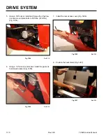
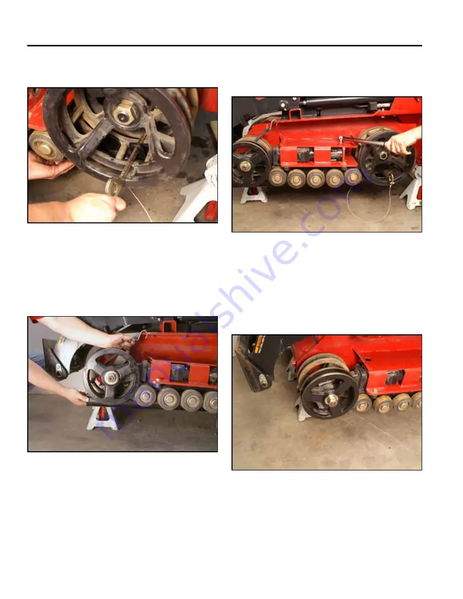
5. Secure the notched end with the pin (Fig. 1272).
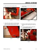
7. Torque the 4 track guide mounting bolts to 75 ft-lbs.
(102 Nm) (Fig. 1274).
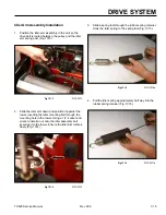
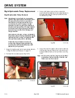
10. Install the track. Refer to “Wide Track Installation”
on page 7-70, or “Narrow Track Installation” on page
7-73.
Fig 1272
PICT-4484
Fig 1274
PICT-4493
8. Remove the alignment tool.
9. Wide track models only: Remove the nut and
washer/tensioner wheel assembly from the tensioner
arm wheel shaft (Fig. 1275).
6. Rotate the tool and move the track guide as neces-
sary until the tool fits into the track guide channel.
Secure the end of the alignment tool with a strap
(Fig. 1273).
Fig 1275
PICT-4483
Fig 1273
PICT-4488a
Summary of Contents for Dingo TX 525
Page 1: ...TX525 Service Manual Sitework Systems Form No 492 9195...
Page 3: ...ii Rev 000 TX525 Service Manual 8 01 10 Revision 000 REVISIONS...
Page 11: ...x Rev 000 TX525 Service Manual TABLE OF CONTENTS THIS PAGE INTENTIONALLY LEFT BLANK...
Page 243: ...ENGINE 4 190 Rev 000 TX525 Service Manual THIS PAGE INTENTIONALLY LEFT BLANK...
Page 263: ...ELECTRICAL 5 20 Rev 000 TX525 Service Manual THIS PAGE INTENTIONALLY LEFT BLANK...
Page 377: ...HYDRAULIC SYSTEM 6 114 Rev 000 TX525 Service Manual THIS PAGE INTENTIONALLY LEFT BLANK...
Page 479: ...DRIVE SYSTEM 7 102 Rev 000 TX525 Service Manual THIS PAGE INTENTIONALLY LEFT BLANK...
Page 553: ...HYDRAULIC TESTING 9 20 Rev 000 TX525 Service Manual THIS PAGE INTENTIONALLY LEFT BLANK...


