DRIVE SYSTEM
7-40
Rev. 000
TX525 Service Manual
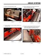
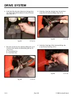
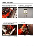
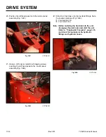
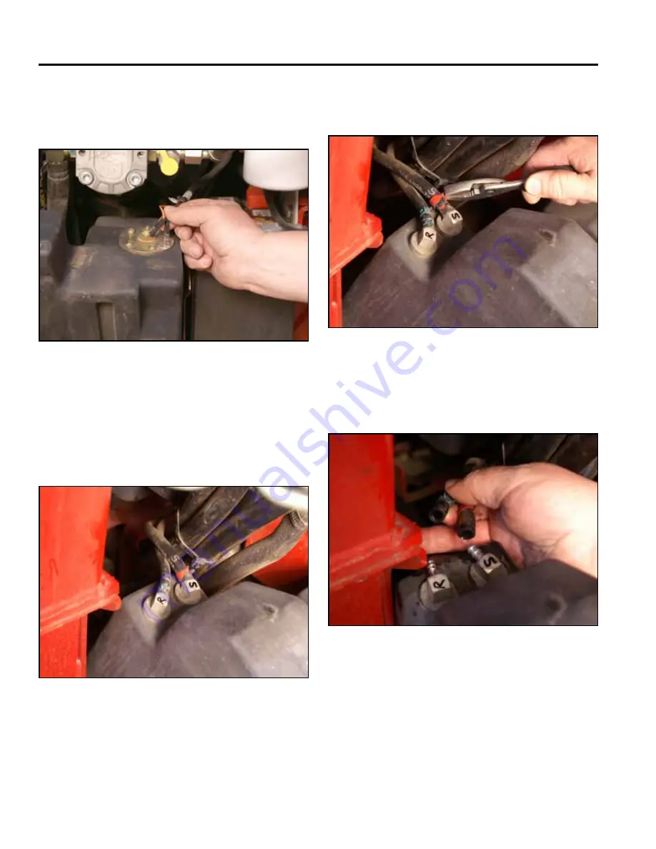
6. Disconnect the two wires (black and orange) from
the fuel sending unit located on the top of the fuel
tank (Fig. 1411).
Fig 1411
PICT-4262a
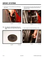
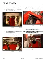
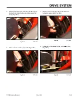
7. Mark the suction fuel line and tank fitting with an “S”
and the return fuel line and tank fitting with an “R”
(Fig. 1412):
S - Fuel suction line
R - Fuel return line
Fig 1412
PICT-4263
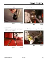
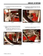
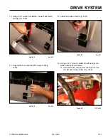
8. Slide the 2 fuel hose clamps down the fuel lines
away from the fuel tank fittings (Fig. 1413).
Fig 1413
PICT-4264
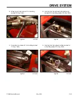
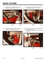
9. Slide the 2 fuel lines off the fuel tank fittings. Re-
move the fuel tank (Fig. 1414).
Fig 1414
PICT-4265
Summary of Contents for Dingo TX 525
Page 1: ...TX525 Service Manual Sitework Systems Form No 492 9195...
Page 3: ...ii Rev 000 TX525 Service Manual 8 01 10 Revision 000 REVISIONS...
Page 11: ...x Rev 000 TX525 Service Manual TABLE OF CONTENTS THIS PAGE INTENTIONALLY LEFT BLANK...
Page 243: ...ENGINE 4 190 Rev 000 TX525 Service Manual THIS PAGE INTENTIONALLY LEFT BLANK...
Page 263: ...ELECTRICAL 5 20 Rev 000 TX525 Service Manual THIS PAGE INTENTIONALLY LEFT BLANK...
Page 377: ...HYDRAULIC SYSTEM 6 114 Rev 000 TX525 Service Manual THIS PAGE INTENTIONALLY LEFT BLANK...
Page 479: ...DRIVE SYSTEM 7 102 Rev 000 TX525 Service Manual THIS PAGE INTENTIONALLY LEFT BLANK...
Page 553: ...HYDRAULIC TESTING 9 20 Rev 000 TX525 Service Manual THIS PAGE INTENTIONALLY LEFT BLANK...


