BRAKES
8-4
Rev. 000
TX525 Service Manual
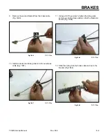
14. Using two 7/16” sockets, remove the 2 bolts and
nuts holding the left hand brake plate to the brake
mounting bracket (the socket/ratchet on the bolt
head should be 1/4” drive to clear the oil pan) (Fig.
1646).
Fig 1646
PICT-4325
15. Push the 2 brake plates outward toward the drive
wheels (Fig. 1647).
Note: The drive wheels may have to rotate to permit
the brake plates to extend fully outward.
Fig 1647
PICT-4327
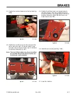
16. Position the brake handle in the ON position.
17. Using a 3/8” socket, remove the 4 bolts that secure
the top right panel to the control panel assembly
(Fig. 1648).
Fig 1648
PICT-4268
18. Remove the right panel from the control panel
assembly (Fig. 1649).
Fig 1649
PICT-4269
Summary of Contents for Dingo TX 525
Page 1: ...TX525 Service Manual Sitework Systems Form No 492 9195...
Page 3: ...ii Rev 000 TX525 Service Manual 8 01 10 Revision 000 REVISIONS...
Page 11: ...x Rev 000 TX525 Service Manual TABLE OF CONTENTS THIS PAGE INTENTIONALLY LEFT BLANK...
Page 243: ...ENGINE 4 190 Rev 000 TX525 Service Manual THIS PAGE INTENTIONALLY LEFT BLANK...
Page 263: ...ELECTRICAL 5 20 Rev 000 TX525 Service Manual THIS PAGE INTENTIONALLY LEFT BLANK...
Page 377: ...HYDRAULIC SYSTEM 6 114 Rev 000 TX525 Service Manual THIS PAGE INTENTIONALLY LEFT BLANK...
Page 479: ...DRIVE SYSTEM 7 102 Rev 000 TX525 Service Manual THIS PAGE INTENTIONALLY LEFT BLANK...
Page 553: ...HYDRAULIC TESTING 9 20 Rev 000 TX525 Service Manual THIS PAGE INTENTIONALLY LEFT BLANK...


