Note:
Rotate the bolt clockwise to raise the
deck; rotate the bolt counterclockwise to lower it.
3.
Tighten the jam nuts and side bolts.
4.
Check the front-to-rear pitch; refer to
the Mower Deck Front-to-Rear Pitch (page 52)
.
Matching the Height-of-Cut
1.
Check the rear tire pressure.
2.
Set the height-of-cut to the 76 cm (3 inches)
position; refer to
(page 20)
.
3.
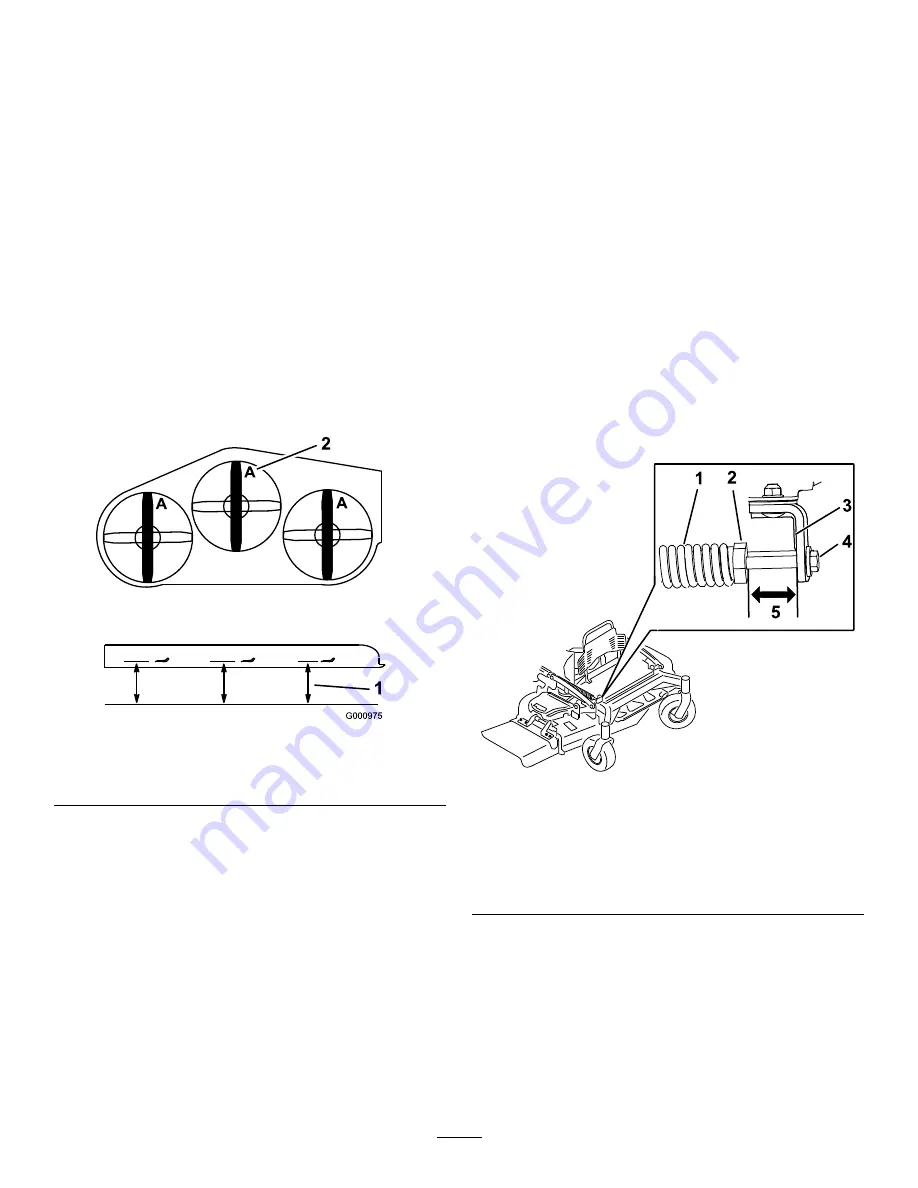
With the machine on level surface, position 1
blade front-to-rear.
4.
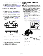
Measure at
A
, and from a level surface to the
cutting edge of the blade tips (
).
Note:
The measurement should be 76 cm (3
inches).
g000975
Figure 91
1.
Measure from a level
surface
2.
Measure the blade at point
A
5.
If the measurement is not correct, locate the
front 2 yokes on the machine (
).
6.
Loosen the side bolt and jam nut of the yokes.
7.
Adjust the top bolt of the yokes until the blade
tips match 76 cm (3 inches).
8.
Tighten the jam nuts and side bolts.
Adjusting the Deck-Lift
Spring
Note:
Adjusting the compression spring alters how
much the deck floats and the amount of effort needed
to lift the deck when using the height-of-cut lever.
•
More spring extension reduces the lever lift force
required and causes the deck to float more.
•
Less spring extension increases the lever lift force
required and causes the deck to float less.
1.
Raise the height-of-cut lever and lock it into the
transport position.
2.
Check the distance between the spring nut
and the rear side of the welded mount bracket
(
).
3.
Ensure that the length is between 47 to 50 mm
(1.8 to 2 inches) as shown in
.
4.
If needed, adjust the distance by adjusting the
bolt on the front of the mount bracket (
).
g301337
Figure 92
1.
Deck-lift spring
4.
Adjustment bolt
2.
Spring nut
5.
Length is between 47 to
50 mm (1.8 to 2 inches).
3.
Rear side of the mount
bracket
5.
Repeat this procedure for the opposite deck-lift
spring.
53
Summary of Contents for GrandStand 72504TE
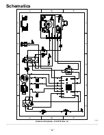
Page 58: ...Schematics g302050 Electrical Schematic 140 1878 Rev A 58 ...
Page 59: ...Notes ...


