23
MAINTENANCE
CAUTION
Before servicing or making adjustments to the
machine, stop engine and remove key from
the switch.
ENGINE CARE
The Engine Manual supplied with your Greens Aerator
provides the maintenance procedures for service of
the air cleaner, oil requirements, ignition components,
etc.
Note:
If Greens Aerator is to be operated at altitudes of
3000 feet or above sea level, it may require a high
altitude carburetor main jet. Order Part No. 8055537
from your Authorized Briggs & Stratton Service Dealer.
CHANGING HYDRAULIC SYSTEM OIL
The hydraulic system oil must be changed immediately
when any contamination, sludge, water or
condensation appears.
1.
Remove tines from tine blocks and lower coring
head; refer to Install Tines.
2.
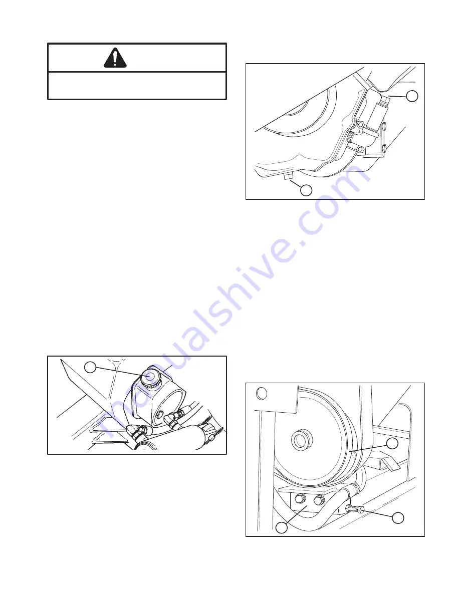
Position a drain pan under chassis below pump
assembly (Fig. 28).
3.
Remove hose clamp securing return hose to
pump. Disconnect hose from pump allowing oil to flow
into drain pan.
4.
Connect return hose to pump and secure with
hose clamp.
1. Pump reservoir
Figure 28
1
5.
Fill pump reservoir; refer to checking Hydraulic
System Fluid.
6.
Check all connections for possible leaks.
CHANGE TRANSAXLE OIL
Each year oil in transaxle must be changed. If possible
run machine just before changing oil. Warm oil flows
more freely and carries more contaminants than cold
oil.
1.
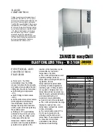
Place a drain pan below drain plug on axle. Clean
area around drain plug (Fig. 29).
1. Drain plug
2. Fill plug
Figure 29
1
2
2.
Remove drain plug and allow oil to flow into drain
pan. After oil is drained, reinstall drain plug.
3.
Remove fill plug (Fig. 29) and pour approx. 64 oz.
of SAE E.P. 90 wt. oil into extension tube. Stop when oil
level reaches top of tube.
4
. To check oil level in the future: remove plug, and
add oil as required to bring level to top of tube.
BELT ADJUSTMENTS
Make sure belts are properly tensioned to assure
correct operation of unit and unnecessary wear. Check
all belts midway in the span of the belt.
1.
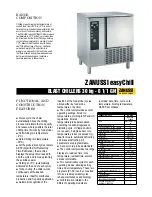
The belt tension on the hydraulic pump (Fig. 30)
must have a maximum deflection of 5/32 of an inch with
a 2 to 3 pound load applied.
1. Hydraulic pump belt
2. Pump support bracket
3. Adjusting screw
Figure 30
1
3
2


