Greensmaster 3320/3420
Hydraulic System
Page 5 -- 35
CAUTION
Prevent personal injury and/or damage to equip-
ment. Read all WARNINGS, CAUTIONS and Pre-
cautions for Hydraulic Testing at the beginning
of this section.
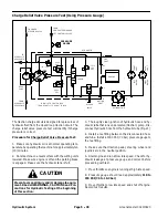
3. Read Precautions for Hydraulic Testing in this sec-
tion.
4. Make sure the traction control assembly is adjusted
to the neutral position.
5. Attach a heavy chain to the rear of the machine frame
and an immovable object to prevent the machine from
moving during testing.
6. If machine has 3 wheel drive (optional kit), block up
the rear wheel off the ground to allow flow through the
rear wheel motor.
7. Chock front wheel being tested to prevent rotation of
the wheel.
8. Thoroughly clean junction of hydraulic lines and fit-
ting on front wheel motor that is
not
being tested. Dis-
connect hydraulic lines from front wheel motor that is
not
being tested. Cap the disconnected hydraulic lines
and fittings in wheel motor.
9. Thoroughly clean junction of hydraulic hose and
up-
per
hydraulic fitting on front side of piston pump (forward
port). Disconnect hose from upper pump fitting.
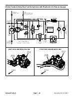
10.Install hydraulic tester (pressure and flow) in series
between piston pump fitting and disconnected hose to
allow flow from piston pump to tester (same tester con-
nections as Piston (Traction) Pump Flow Test). Make
sure that fitting and hose connections are properly tight-
ened. Also, make sure the flow control valve on tester is
fully open.
11. Start engine and run at low idle speed. Check for hy-
draulic leakage and correct before proceeding with test.
CAUTION
Use extreme caution when performing test. The
wheel being tested will be trying to move the ma-
chine.
12.Move throttle so engine is running at high idle speed.
Make sure that functional control lever is in the transport
position.
13.Slowly push traction pedal in
forward
direction until
1000 PSI (69 bar)
is displayed on the tester pressure
gauge. Make sure that wheel motor being tested is not
rotating.
14.Wheel motor internal leakage will be shown on flow
meter. Flow should be
less than 1.5 GPM (5.7 LPM)
for
the tested wheel motor.
15.Release traction pedal to the neutral position and re-
lease brakes. Rotate wheel being tested and retest.
Testing of wheel motor leakage in three (3) different
wheel positions will provide most accurate test results.
16.Release traction and brake pedals. Shut engine off.
Record results of wheel motor leakage test.
17.If specification is not met, the tested wheel motor
needs to be repaired or replaced as necessary.
18.To test second front wheel motor:
A. Reconnect hydraulic lines to untested front wheel
motor.
B. Disconnect and cap hydraulic lines to tested front
wheel motor.
C. Complete steps 11 to 17 for the second front
wheel motor.
19.If machine has 3 wheel drive (optional kit), test rear
wheel motor:
A. Both front wheel motors should have hydraulic
lines connected. Block up both front wheels off the
ground. Front wheels need to turn freely when test-
ing rear wheel motor.
B. Attach a heavy chain to the rear of the machine
frame and an immovable object to prevent the ma-
chine from moving during testing.
C. Position rear wheel on the ground and chock rear
wheel to prevent it from turning.
CAUTION
Use extreme caution when performing test. The
rear wheel will be trying to move the machine.
D. Complete steps 11 to 17 to test rear wheel motor
leakage.
20.When testing is completed, disconnect tester from
hydraulic hose and pump fitting. Connect hose to pump
fitting. Make sure that hydraulic connections at wheel
motors are all secure.
Hy
draulic
Sy
st
em
Summary of Contents for Greensmaster 3420 TriFlex
Page 2: ...Greensmaster 3320 3420 This page is intentionally blank ...
Page 4: ...Greensmaster 3320 3420 This page is intentionally blank ...
Page 6: ...Greensmaster 3320 3420 This page is intentionally blank ...
Page 24: ...Greensmaster 3320 Page 3 6 Gasoline Engine This page is intentionally blank ...
Page 38: ...Greensmaster 3420 Page 4 4 Diesel Engine This page is intentionally blank ...
Page 54: ...Greensmaster 3420 Page 4 20 Diesel Engine This page is intentionally blank ...
Page 56: ...Greensmaster 3320 3420 Hydraulic System Page 5 2 This page is intentionally blank ...
Page 150: ...Greensmaster 3320 3420 Hydraulic System Page 5 96 This page is intentionally blank ...
Page 250: ...Greensmaster 3320 3420 Page 6 100 Electrical System This page is intentionally blank ...
Page 277: ...Greensmaster 3320 3420 Page 7 27 Chassis This page is intentionally blank Chassis ...
Page 325: ...Greensmaster 3320 3420 Groomer Page 9 13 This page is intentionally blank Groomer ...
Page 340: ...Greensmaster 3320 3420 Page 10 2 Foldout Drawings This page is intentionally blank ...
Page 347: ...Page 10 9 This page is intentionally blank ...
Page 356: ...Page 10 18 E Reels Wire Harness Drawing Greensmaster 3320 3420 Serial Number Below 312000000 ...
Page 358: ...Page 10 20 E Reels Wire Harness Drawing Greensmaster 3320 3420 Serial Number Above 312000000 ...
Page 360: ...Page 10 22 This page is intentionally blank ...


