Greensmaster 3320/3420
Hydraulic System
Page 5 -- 43
NOTE:
This steering test procedure will be affected by
incorrect rear tire pressure, binding in the hydraulic
steering cylinder, extra weight on the vehicle and/or
binding of the steering fork assembly. Make sure that
these items are checked before proceeding with any hy-
draulic testing procedure.
Procedure for Power Steering Valve Test:
1. Make sure the hydraulic tank is full.
2. Make sure hydraulic oil is at normal operating tem-
perature by operating the machine for approximately ten
(10) minutes.
3. Perform the Steering/Lift Relief Valve Pressure and
Steering/Lift Circuit Gear Pump Flow Tests to make sure
that relief valve and gear pump are functioning correctly
(see Steering/Lift Relief Valve Pressure and Steering/
Lift Circuit Gear Pump Flow Tests in this section).
4. Drive machine slowly in a figure eight on a flat level
surface.
A. There should be no shaking or vibration in the
steering wheel or rear wheel.
B. Steering wheel movements should be followed
immediately
by a corresponding rear wheel move-
ment
without
the steering wheel continuing to turn.
5. Stop the unit with the engine running. Turn steering
wheel with small quick movements in both directions.
Let go of the steering wheel after each movement.
A. The steering wheel must go back immediately to
the neutral position.
B. The steering wheel should
not
continue to turn.
NOTE:
The steering wheel must be able to turn with no
more than
45 in--lb (5.1 N--m)
of torque.
6. If either of these performance tests indicate a steer-
ing problem, determine if the steering cylinder is faulty
using the following procedure.
A. Park machine on a level surface with the cutting
units lowered and off. Make sure engine is off and the
parking brake is engaged.
B. Turn the steering wheel all the way to the left
(counterclockwise) so the steering cylinder rod is ful-
ly extended.
C. Turn engine off.
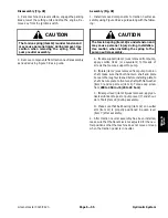
CAUTION
Prevent personal injury and/or damage to equip-
ment. Read all WARNINGS, CAUTIONS and Pre-
cautions for Hydraulic Testing at the beginning
of this section.
D. Read Precautions for Hydraulic Testing.
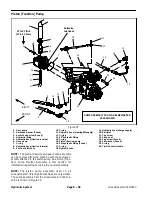
E. Remove hydraulic hose from the fitting on the ball
joint end of the steering cylinder (Fig. 26). Plug the
end of the hose.
F. With the engine off, continue turning the steering
wheel to the left (counterclockwise) with the steering
cylinder fully extended. Observe the open fitting on
the steering cylinder as the steering wheel is turned.
If oil comes out of the fitting while turning the steering
wheel to the left, the steering cylinder has internal
leakage and must be repaired or replaced.
G. When steering cylinder testing is completed, re-
move plug from the hydraulic hose. Connect hose to
the steering cylinder fitting.
7. If steering problem exists and steering cylinder
tested acceptably, power steering valve requires ser-
vice (see Power Steering Valve and Power Steering
Valve Service in the Service and Repairs section of this
chapter).
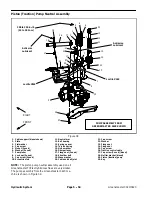
Figure 26
1
2
1. Steering cylinder
2. Ball joint end hose
Hy
draulic
Sy
st
em
Summary of Contents for Greensmaster 3420 TriFlex
Page 2: ...Greensmaster 3320 3420 This page is intentionally blank ...
Page 4: ...Greensmaster 3320 3420 This page is intentionally blank ...
Page 6: ...Greensmaster 3320 3420 This page is intentionally blank ...
Page 24: ...Greensmaster 3320 Page 3 6 Gasoline Engine This page is intentionally blank ...
Page 38: ...Greensmaster 3420 Page 4 4 Diesel Engine This page is intentionally blank ...
Page 54: ...Greensmaster 3420 Page 4 20 Diesel Engine This page is intentionally blank ...
Page 56: ...Greensmaster 3320 3420 Hydraulic System Page 5 2 This page is intentionally blank ...
Page 150: ...Greensmaster 3320 3420 Hydraulic System Page 5 96 This page is intentionally blank ...
Page 250: ...Greensmaster 3320 3420 Page 6 100 Electrical System This page is intentionally blank ...
Page 277: ...Greensmaster 3320 3420 Page 7 27 Chassis This page is intentionally blank Chassis ...
Page 325: ...Greensmaster 3320 3420 Groomer Page 9 13 This page is intentionally blank Groomer ...
Page 340: ...Greensmaster 3320 3420 Page 10 2 Foldout Drawings This page is intentionally blank ...
Page 347: ...Page 10 9 This page is intentionally blank ...
Page 356: ...Page 10 18 E Reels Wire Harness Drawing Greensmaster 3320 3420 Serial Number Below 312000000 ...
Page 358: ...Page 10 20 E Reels Wire Harness Drawing Greensmaster 3320 3420 Serial Number Above 312000000 ...
Page 360: ...Page 10 22 This page is intentionally blank ...


