background image

Greensmaster Flex 1800/1820/2100/2120

Belt Driven Groomer (Optional)

Page 8 

 18

Grooming Reel Bearing Replacement

Bearing Removal

1. Position machine on a clean and level surface with

engine stopped. Engage parking brake.

2. Remove the cutting unit from the machine and place

cutting unit on a flat work area.

3. To remove groomer RH drive plate assembly from

right side of cutting unit, remove front roller, grooming

reel and then drive plate assembly (see Grooming Reel

(Forward Rotating or Counter Rotating) in this section).

4. To remove LH support plate assembly from left side

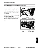
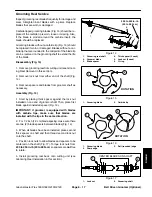
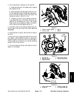
of cutting unit (Fig. 18):

A.  Remove reel drive cover, drive belt, reel pulley

and then reel drive assembly from cutting unit (see

Reel Drive Assembly in the Service and Repairs sec-

tion of Chapter 4 

 Traction and Reel Drive System).

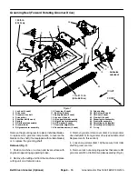
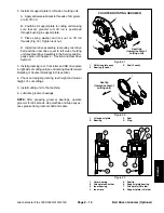
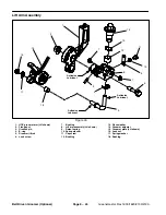
B.  Remove lock nut and spring washer that secure

LH groomer arm lift rod to LH support plate (Fig. 19).

Remove support plate from cutting unit.

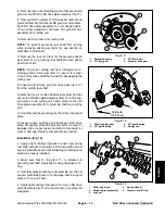
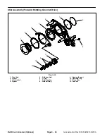
5. Remove grooming reel seals and bearings from RH

drive plate and LH support plate assemblies (Figs. 20,

21 and 22). Discard all removed seals and bearings.

Bearing Installation

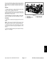
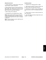
1. Install new grooming reel bearings and seals into RH

drive plate and LH support plate assemblies (Fig. 23):

IMPORTANT: Bearings should be installed with ex-

tended inner races toward center of housing. Also,

apply pressure equally to inner and outer bearing

races when installing bearings.

A.  Press new outer bearing fully to shoulder of RH

drive plate bore. Then, install new inner bearing until

inner race contacts outer bearing race.

B. Press new bearing into LH support plate until it is

flush with shoulder of bearing bore.

C. Install new seals into groomer side plates. 

NOTE:

Seals should be installed so the lip side of the seal

will face the center of the cutting reel. When bearings

are greased, grease will purge from inner seals.

1. Cutting 

unit

2.  Reel drive assembly

3.  LH support plate

Figure 18

1

3

2

1.  Roller cap screw

2.  Grooming reel assembly

3. Lock 

nut

4. Spring 

washer

5.  Groomer arm lift rod

Figure 19

4

2

1

3

5

1.  RH drive plate assy

2.  Bearing (2 used)

3.  Seal (2 used)

Figure 20

Seal lips

(toward center of

cutting unit)

3

2

2

3

1

FORWARD ROTATING GROOMER

Summary of Contents for Greensmaster Flex 1820

Page 1: ...Form No 12188SL Rev D Greensmaster Flex 1800 1820 2100 2120 Models 04040 04041 04044 and 04045 Original Instructions EN...

Page 2: ...ment shall not be reproduced by a third party without the express written consent of The Toro Company and or the appropriate affiliated company Revision History Revision Date Description 2012 Initial...

Page 3: ...lications To do this effectively we encourage user feedback Please comment on the completeness accuracy organization usability and readability of this manual by an e mail to servicemanuals toro com or...

Page 4: ...NOTES _...

Page 5: ...d Parts Catalogs for your machine Replacement Operator s Manuals and Parts Catalogs are available on the internet at www toro com The Toro Company reserves the right to change product specifications o...

Page 6: ...Greensmaster Flex 1800 1820 2100 2120 This page is intentionally blank...

Page 7: ...iring Schematics 5 4 Wire Harnesses 5 6 Special Tools 5 8 Troubleshooting 5 10 Component Testing 5 11 Chapter 6 Chassis and Controls Specifications 6 2 General Information 6 3 Service and Repairs 6 4...

Page 8: ...Greensmaster Flex 1800 1820 2100 2120 This page is intentionally blank...

Page 9: ...master Flex 1800 1820 2100 2120 Page 1 1 Safety Chapter 1 Safety Table of Contents SAFETY INSTRUCTIONS 2 Before Operating 2 While Operating 3 Maintenance and Service 3 SAFETY AND INSTRUCTION DECALS 4...

Page 10: ...devices and decals in place If a shield safety device or decal is malfunctioning illeg ible or damaged repair or replace it before operating the machine 5 Always wear substantial shoes Do not operate...

Page 11: ...e is to be transported on a trailer or in a vehicle Maintenance and Service 1 The Traction Unit and Cutting Unit Operator s Manu als provide information regarding the operation general maintenance and...

Page 12: ...als Safety decals and instructions are easily visible to the operator and are located near any area of potential dan ger Replace any decal that is damaged or lost Decal part numbers are listed in your...

Page 13: ...Metric Fasteners 5 Other Torque Specifications 6 Conversion Factors 6 Product Records Insert Operator s Manual and Parts Catalog for your Greensmaster Flex machine at the end of this section Addition...

Page 14: ...0 09375 Greensmaster Flex 1800 1820 2100 2120 Page 2 2 Product Records and Maintenance Equivalents and Conversions...

Page 15: ...evailing torque feature e g Nylock nut hardness of the surface underneath the fastener s head or similar condition which affects the installation As noted in the following tables torque values should...

Page 16: ...3 41 4 43 5 58 7 3 8 24 UNF 17 2 18 2 24 3 35 4 47 5 50 6 68 8 7 16 14 UNC 27 3 27 3 37 4 50 5 68 7 70 7 95 9 7 16 20 UNF 29 3 29 3 39 4 55 6 75 8 77 8 104 11 1 2 13 UNC 30 3 48 7 65 9 75 8 102 11 105...

Page 17: ...ft lb 126 14 N m M16 X 2 0 166 17 ft lb 225 23 N m 229 23 ft lb 310 31 N m M20 X 2 5 325 33 ft lb 440 45 N m 450 46 ft lb 610 62 N m NOTE Torque values may have to be reduced when installing fastener...

Page 18: ...UNC 200 100 in lb Wheel Bolts and Lug Nuts Thread Size Recommended Torque 7 16 20 UNF Grade 5 65 10 ft lb 88 14 N m 1 2 20 UNF Grade 5 80 10 ft lb 108 14 N m M12 X 1 25 Class 8 8 80 10 ft lb 108 14 N...

Page 19: ...Contents SPECIFICATIONS 3 GENERAL INFORMATION 4 Operator s Manual 4 Fuel Evaporative Control System 4 ADJUSTMENTS 5 Throttle Cable Adjustment 5 SERVICE AND REPAIRS 6 Cooling System 6 Spark Plug 7 Igni...

Page 20: ...Greensmaster Flex 1800 1820 2100 2120 Page 3 2 Engine This page is intentionally blank...

Page 21: ...nical flyweight Low Idle Speed no load 1465 to 1665 RPM High Idle Speed no load 3190 to 3340 RPM Direction of rotation Clockwise facing PTO shaft Fuel Unleaded automotive grade gasoline Fuel Tank Capa...

Page 22: ...are supplied through your local Toro distributor Be prepared to provide your dis tributor with the Toro model and serial number Operator s Manual The Operator s Manual provides information regarding t...

Page 23: ...tle cable to the gov ernor lever 6 After cable adjustment connect spark plug wire to spark plug start engine and allow it to warm to operating temperature Check engine speed with a tachometer A Low id...

Page 24: ...rized water Water could enter and contaminate the fuel system 2 Clean cooling fins on cylinder and cylinder head Re move engine cylinder shroud from engine for more thor ough cleaning Fig 2 3 Clean bl...

Page 25: ...T Replace a cracked fouled or dirty spark plug Do not sand blast scrape or clean spark plug electrodes because engine damage could re sult from grit entering cylinder 4 Set spark plug electrode gap fr...

Page 26: ...tiseize Lubricant 65 in lb 7 3 N m Engine Removal Fig 5 1 Park machine on a level surface with the engine OFF Remove spark plug wire from the spark plug to prevent the engine from starting Close fuel...

Page 27: ...leeve remove en gine base assembly from machine 6 If necessary remove engine from engine base A Remove cap screws item 7 flat washers item 11 and flange nuts item 8 that secure engine to en gine base...

Page 28: ...oss of en gine base Install and finger tighten flange head screw item 9 and hardened washer item 10 that secure engine base to frame G Position front of engine base to align engine and transmission co...

Page 29: ...outer surface of the sleeve is basically straight while the lines above and below are curved in different directions Fig 9 As the coupler wears with normal machine use the curved lines may visually st...

Page 30: ...Greensmaster Flex 1800 1820 2100 2120 Page 3 12 Engine This page is intentionally blank...

Page 31: ...lutch Adjustment 1820 2120 9 SERVICE AND REPAIRS 11 Reel Drive Belt 11 Reel Drive Assembly 12 Reel Drive Bearing Housing 14 Drum Drive Belt 16 Drum Drive Idler Assembly 18 Traction Drums 20 Differenti...

Page 32: ...tomatic Transmission Fluid or equivalent 10 oz 296 ml Traction Drive Transmission to Traction Drive uses Multi Ribbed Poly V Belt Belt Tension Maintained by Spring Loaded Idler Pulley Differential Spu...

Page 33: ...machine on a level surface Make sure engine is OFF Remove spark plug wire from the engine spark plug 2 Locate the traction engage disengage lever next to the RH drive housing drum Fig 1 CAUTION Be ca...

Page 34: ...the transmission en gage disengage lever The lever is spring loaded and may cause personal injury 3 To disengage the spring loaded idler from the trans mission drive belt use a 3 8 wrench to rotate th...

Page 35: ...lls to allow a 5 32 pin to extend through socket A modified socket with ground slots is shown in Figure 5 Modified Socket Use Fig 6 IMPORTANT Avoid using excessive clamping pressure on the reel clutch...

Page 36: ...crews from drive pulleys that are to be removed Slide pulleys from shafts 4 Apply antiseize lubricant to top of woodruff keys Ar range pulleys on reel drive assembly as needed for de sired clip freque...

Page 37: ...t screw in reel clutch lever until reel clutch hub causes the tips of the reel drive hub teeth to contact the mating reel clutch pulley 7 While maintaining light pressure on reel clutch lever rotate s...

Page 38: ...tion assembly and mounting plate Fig 12 Clearance should be from 0 025 to 0 045 0 7 to 1 1 mm 3 To adjust clearance remove mounting plate item 5 in Fig 12 assembly and change shim locations item 6 in...

Page 39: ...ithout extending the extension spring up to 0 030 0 8 mm slack is permissible The distance from the cable bracket to the clutch lever pin center should be 2 5 63 5 mm when the clutch lever is disengag...

Page 40: ...Greensmaster Flex 1800 1820 2100 2120 Traction and Reel Drive System Page 4 10 This page is intentionally blank...

Page 41: ...l surface Make sure engine is OFF Remove spark plug wire from the spark plug 2 Using a 5 8 16mm wrench rotate and hold the bearing housing to allow reel drive belt installation Fig 15 3 Place a new dr...

Page 42: ...19 Reel drive cover 20 Shoulder bolt 21 Spring pin 22 Woodruff key 3 used 23 Set screw 2 used per pulley 24 Ball bearing 2 used 25 Spacer 26 Push nut 27 Cutting unit 28 Flange head screw Figure 16 FRO...

Page 43: ...assembly item 12 NOTE Reel pulleys items 8 11 and 14 can be identi fied by color and number of teeth Pulley location can vary based on desired cutting unit clip frequency see Cutting Unit Clip Adjustm...

Page 44: ...ve Bearing Housing 1 Retaining ring 2 Reel input shaft 3 Bearing 2 used 4 Bearing spacer 5 Wave washer 6 Flocked bearing shield 7 Wave spring 8 Flat washer 9 Retaining ring 10 Bearing housing 11 Sprin...

Page 45: ...ng housing components Assembly Fig 18 1 If bearings were removed from reel input shaft install new bearings onto shaft Press first bearing fully onto shaft Position spacer on shaft and then press seco...

Page 46: ...m The drum drive system on Flex machines uses a multi ribbed poly V drive belt on the right side of the traction drum Removal Fig 19 1 Park machine on a level surface Make sure engine is OFF Remove s...

Page 47: ...l pulley Slide ends of brake band onto brake clevis and brake mount pins Secure brake band to brake clevis pin with retaining ring item 6 5 Make sure that wave washer item 4 is pressed into bore of dr...

Page 48: ...level surface Make sure engine is OFF Remove spark plug wire from the engine spark plug 2 Remove transport wheels if attached see Transport Wheels in the Service and Repairs section of Chapter 6 Chass...

Page 49: ...ening shoulder screw 3 Carefully secure the end of the extension spring item 9 to idler arm 4 Make sure that wave washer item 4 is pressed into bore of drum drive cover 5 Position new gasket item 3 to...

Page 50: ...Lock collar 28 Pin 29 Thrust washer 30 O ring Figure 24 FRONT RIGHT Lubricant Antiseize 1 3 4 5 6 7 8 9 14 17 18 19 20 21 22 23 24 27 29 3 17 6 3 3 22 28 30 2 26 10 11 12 13 15 16 14 25 70 to 80 ft lb...

Page 51: ...and remove jam nut item 11 from long spur gear 14 Remove RH traction drum item 10 from machine Locate and retrieve square key from spur gear NOTE If removal of the drum shaft item 7 long spur gear it...

Page 52: ...m 11 Insert bar stock or other suitable tool through spokes of LH traction drum to keep drum from turning 12 Make sure that ball bearing item 14 is pressed onto the bearing nut item 15 While retaining...

Page 53: ...Greensmaster Flex 1800 1820 2100 2120 Traction and Reel Drive System Page 4 23 This page is intentionally blank Traction and Reel Drive System...

Page 54: ...er 22 Retaining ring 2 used 23 Brake lever 24 Retaining ring 25 LH side plate 26 Washer head screw 27 Lock collar 28 Pin 29 Thrust washer 30 O ring 31 Spur gear assembly Figure 27 FRONT RIGHT Lubrican...

Page 55: ...long spur gear item 8 was removed from drum drive housing slide gear into ball bearing in drive hous ing 2 If spur gear assembly Fig 29 was taken apart as semble as necessary A Press new ball bearing...

Page 56: ...nal components positioned on cover For assembly pur poses note that index mark on housing is aligned with a gear pin that has one 1 gear Fig 33 5 Note locations of projections on inside of cover for...

Page 57: ...assembly Fig 31 5 After housing is installed use one of the spur gears see Differential Assembly in this section to rotate dif ferential gears making sure that they rotate freely with out binding If...

Page 58: ...n a level surface Make sure engine is OFF 2 Remove engine from machine see Engine Removal in the Service and Repairs section of Chapter 3 En gine 3 Use tips of needle nose pliers to spread ends of dri...

Page 59: ...to trans mission 5 Install seven 7 washer head screws to secure cov er to transmission Tighten screws as follows A First using an alternating crossing pattern torque all screws from 15 to 40 in lb 1 7...

Page 60: ...ap screw 2 used 9 Idler pulley bushing 2 used 10 Ball bearing 6 used 11 Idler pulley 2 used 12 Idler pulley 13 Shoulder screw 14 Retaining ring FRONT RIGHT 15 to 17 ft lb 21 to 23 N m 3 1 2 4 9 10 11...

Page 61: ...ings that support idler pulleys are pressed into the pulleys A If bearings were removed from idler pulleys press new bearings fully to shoulder of idler pulleys B If extension spring item 4 was remove...

Page 62: ...from the machine is not neces sary to service the transmission reel drive system Transmission reel drive components can be accessed by removing the battery pack from the frame removing the transmissi...

Page 63: ...s If necessary remove pivot pins item 15 and separate fork from hub 6 Use modified socket see Special Tools in this chap ter to remove bearing collar assembly from clutch shaft Fig 41 IMPORTANT To pre...

Page 64: ...needs to be positioned to ward the reel brake ring item 11 which is pressed into the transmission housing 9 Carefully secure reel brake disc item 14 to reel drive hub item 18 with retaining ring item...

Page 65: ...e Remove ball bearing from reel clutch shaft and discard bearing after shaft has been removed from housing see Transmission Reel Drive System in this section for bearing remov al information 4 Clean a...

Page 66: ...3 24 2 17 15 18 4 8 25 2 See text for tightening procedure See text for tightening procedure Transmission removal from the machine is not neces sary to service the transmission clutch system Trans mis...

Page 67: ...earing on clutch shaft C Press new outer ball bearing item 9 onto clutch shaft D Install flocked bearing shield item 10 wave spring item 11 and flat washer item 12 onto clutch shaft Secure with retain...

Page 68: ...18 Retaining ring Figure 47 2 3 6 8 9 10 11 13 1 5 7 12 14 15 16 17 18 4 1 1 3 4 6 NOTE Mounting plate item 5 thrust friction assembly item 10 rotating housing item 13 hub item 14 drive inserts item...

Page 69: ...5 thrust friction assembly item 10 rotating housing item 13 hub item 14 drive in serts item 16 or fixed housing item 17 is worn or dam aged replace clutch assembly Clutch Assembly Fig 47 1 Press new b...

Page 70: ...7 Set screw 2 used 18 Washer head screw 4 used 19 Torsion spring 20 Shoulder screw 21 Lock nut 22 Traction clutch cable 23 Spring anchor 24 Transmission housing FRONT 15 to 17 ft lb 21 to 23 N m 2 3 6...

Page 71: ...with four 4 washer head screws item 18 Tighten screws as follows A First torque all four 4 screws from 15 to 40 in lb 1 7 to 4 5 N m B Then torque all screws from 85 to 95 in lb 9 6 to 10 7 N m 2 Pos...

Page 72: ...to 11 ft lb 12 to 14 N m See text for tightening procedure 9 to 11 ft lb 12 to 14 N m See text for tightening procedure The following procedure can be used to remove the clutch shaft assembly from the...

Page 73: ...or on clutch shaft assembly Fig 51 4 Secure actuator pin into clutch housing with locator pin item 7 Make sure that locator pin is inserted in slot in actuator pin 5 Secure clutch shaft assembly in cl...

Page 74: ...8 9 10 1 5 7 4 3 11 13 12 14 15 16 17 18 19 20 21 22 23 24 25 26 27 28 Clutch Shaft Disassembly Fig 52 NOTE Several bearings used in the clutch shaft as sembly are a pressed fit so a press is require...

Page 75: ...and 7 and bearing spacer item 6 from upper side of pulley Discard re moved bearings 11 Remove oil seal item 9 from clutch pulley taking care to not damage seal bore in pulley Note orientation of oil...

Page 76: ...all re taining ring item 13 to secure bearing 9 Press bearing item 7 onto clutch shaft and into clutch pulley Bearing should be pressed fully until it con tacts shoulder on shaft 10 Slide bearing spac...

Page 77: ...Greensmaster Flex 1800 1820 2100 2120 Traction and Reel Drive System Page 4 47 This page is intentionally blank Traction and Reel Drive System...

Page 78: ...n drum drive system shown in Figure 55 Transmission drum drive compo nents can be accessed by removing the engine from the frame removing the transmission cover and then re moving the drive belt Disas...

Page 79: ...using with washer head screws First torque all washer head screws from 15 to 40 in lb 1 7 to 4 5 N m Then using an alternat ing crossing pattern torque all screws from 85 to 95 in lb 9 6 to 10 7 N m E...

Page 80: ...moving the transmission cover and then removing the drive belt If transmission removal is desired proceed with the fol lowing steps Once the transmission has been removed from the machine service proc...

Page 81: ...oles with frame and RH drum housing Install and finger tighten fasteners to secure transmission to machine A Four 4 washer head screws item 7 that secure extension housing item 13 to RH drum housing B...

Page 82: ...Greensmaster Flex 1800 1820 2100 2120 Traction and Reel Drive System Page 4 52 This page is intentionally blank...

Page 83: ...FORMATION 3 Operator s Manual 3 WIRING SCHEMATICS 4 WIRE HARNESSES 6 SPECIAL TOOLS 8 TROUBLESHOOTING 10 Starting Problems 10 COMPONENT TESTING 11 Ignition System Operation 11 On Off Switch 12 Optional...

Page 84: ...Greensmaster Flex 1800 1820 2100 2120 Page 5 2 Electrical System This page is intentionally blank...

Page 85: ...on Operator s Manual The Traction Unit Operator s Manual provide informa tion regarding the operation general maintenance and maintenance intervals for your Greensmaster machine Refer to this Operator...

Page 86: ...T Subaru Engine ON OFF SWITCH is open in the ON position TRACTION SWITCH is closed when traction lever is in neutral HIGH TENSION LEAD FLYWHEEL CONNECTOR LIGHTING COIL ORANGE HOUR YELLOW CONNECTOR VIO...

Page 87: ...parking brake latch is engaged machine serial numbers above 400000000 A B C D E F BLACK BLACK BLACK BLACK VIOLET BLUE RED WHITE YELLOW TRACTION SWITCH ENGINE MAGNETO INTERLOCK MODULE IGNITION COIL HIG...

Page 88: ...e Harness Drawing Wire Harness Diagram P06 PARKING BRAKE LATCH P02 TRACTION SWITCH J02 ENGINE MAGNETO P01 J01 ENGINE GROUND J03 HOUR METER P05 ON OFF SWITCH SWITCH PARKING BRAKE LATCH SWITCH TRACTION...

Page 89: ...2100 2120 Page 5 7 Electrical System Wire Harness Drawing Wire Harness Diagram machine serial numbers above 400000000 machine serial numbers above 400000000 Drawing No 122 0965 Rev C Drawing No 122 0...

Page 90: ...t allowed through the meter This excess current can cause damage to circuits not designed to carry it Figure 1 Skin Over Grease Special non conductive grease which forms a light pro tective skin to he...

Page 91: ...al System Spark Tester For testing electronic ignitions Saves time because you will know if the ignition is causing the problem on a non starting engine The tester determines if ignition spark is pres...

Page 92: ...lug wire is not connected to spark plug Traction lever is not in the NEUTRAL position An engine problem exists that prevents the engine from running ON OFF switch is faulty Electrical wires are loose...

Page 93: ...g speeds 1 With engine not running remove spark plug wire from the spark plug and connect it to the spark tester see Special Tools in this chapter 2 Connect spring clip of tester to a good unpainted g...

Page 94: ...be tested to determine whether continuity exists between the various terminals for each switch position The switch terminals are marked as shown in Figure 6 The circuitry of the on off switch is show...

Page 95: ...ay be tested to determine whether continuity exists between the various terminals for each switch position The switch terminals are marked as shown in Figure 8 The circuitry of the light switch is sho...

Page 96: ...con necting a multimeter ohms setting across the connec tor terminals 3 With the parking brake latch released there should be no continuity infinite ohms across the switch termi nals 4 Verify that th...

Page 97: ...the connec tor terminals 3 With the traction lever in the NEUTRAL position there should be continuity zero ohms across the switch terminals 4 Verify that the switch opens infinite ohms as the traction...

Page 98: ...ition System Operation in this section 2 Check the operation of both the parking brake latch and traction switches see Parking Brake Latch Switch and Traction Switch in this section Adjust or replace...

Page 99: ...ONS 2 GENERAL INFORMATION 3 Operator s Manual 3 SERVICE AND REPAIRS 4 Handle Assembly 4 Throttle Cable Replacement 6 Brake Cable Replacement 7 Traction Clutch Cable Replacement 8 Reel Clutch Cable Rep...

Page 100: ...Greensmaster Flex 1800 1820 2100 2120 Page 6 2 Chassis and Controls Specifications Item Description Transport Wheel Optional Tire Pressure 12 to 15 PSI 83 to 103 kPa...

Page 101: ...nformation Operator s Manual The Operator s Manual provides information regarding the operation adjustment procedures and general maintenance for your Greensmaster machine Refer to the Operator s Manu...

Page 102: ...ve console cover from handle assembly 3 Disconnect reel clutch traction clutch and brake cables from transmission see Cable Replacement in this section 4 Disconnect throttle cable from engine see Thro...

Page 103: ...is traditionally operated with the handle adjusted to the maximum height 3 Attach reel clutch traction clutch and brake cables to transmission see Cable Replacement in this section Check cable operati...

Page 104: ...Installation 1 Connect throttle cable to throttle control assembly Fig 5 A Secure throttle cable end to pin on throttle control with flat washer and retaining ring B Secure cable housing to throttle...

Page 105: ...andle assembly with a washer and jam nut on each side of the bracket Adjust jam nuts so that equal amount of cable threads are visible above and below jam nuts Leave jam nuts snug until final cable ad...

Page 106: ...the transmission Fig 9 A Loosen front cable jam nut that secures cable to traction cable bracket on transmission Lift cable from bracket B Remove flange nut that secures cable eyelet to transmission b...

Page 107: ...lever with flange nut B Position traction cable to the casting slot of trans mission with a jam nut flat washer and lock washer on each side of the slot Adjust and tighten jam nuts so that equal amou...

Page 108: ...ion Fig 12 A Loosen front cable jam nut and lift cable free from casting slot of transmission B Remove retaining ring that secures cable eyelet to reel clutch lever and slide cable eyelet from lever C...

Page 109: ...f 2 780 to 2 850 70 6 to 72 4 mm D Remove rubber plug at front of transmission to view reel clutch Make sure that reel clutch teeth dis engage when the clutch is released Also verify that clutch teeth...

Page 110: ...ndle 12 Extension spring 13 Latch pin 14 Bushing 10 used 15 Shifter latch 16 Transport lever 17 Reel shift lever 18 Reel cam lever 19 Ball bearing 20 Cap screw 21 Screw 22 Flat washer 23 Flat washer 2...

Page 111: ...purposes Assembly 1 Assemble lever assembly using Figures 14 and 15 as guides A If shift arm link item 4 in Figure 14 was removed from transport lever make sure that tab on shift arm link is position...

Page 112: ...ct reel clutch and traction clutch cables to le ver assembly see Cable Replacement in this section Check cable operation and adjust as necessary 7 Check adjustment of traction switch see Traction Swit...

Page 113: ...Greensmaster Flex 1800 1820 2100 2120 Page 6 15 Chassis and Controls This page is intentionally blank Chassis and Controls...

Page 114: ...locking pin 8 Compression spring 9 Spacer 10 Retaining ring 11 LH side plate 12 Torsion spring Figure 18 FRONT RIGHT 1 2 3 5 6 8 10 12 11 4 7 9 Flex 2100 2120 Shown NOTE The offset handle clamps on Fl...

Page 115: ...y disassemble and remove service posi tion locking pin assembly items 7 8 9 and 10 from rear frame Installation Fig 18 1 Make sure machine is parked on a level surface and the engine is OFF 2 If servi...

Page 116: ...heels Optional 1 Cap screw 3 used 2 Lock washer 3 used 3 Shallow rim 4 Tire 5 Hub 6 Wheel retaining lever 7 Torsion spring 8 Shoulder screw 2 used 9 Cap screw 4 used 10 Deep rim 11 Inner tube 12 Hub b...

Page 117: ...ring and retaining lever from the hub Wheel Assembly Fig 20 1 If shoulder screws were removed from hub apply Loctite 242 or equivalent to threads of shoulder screws Secure torsion spring and retaining...

Page 118: ...Greensmaster Flex 1800 1820 2100 2120 Page 6 20 Chassis and Controls This page is intentionally blank...

Page 119: ...S 11 Backlapping 11 Bedbar Assembly 12 Bedknife Replacement and Grinding 14 Bedbar Adjuster Service 16 Reel Assembly 18 Reel Assembly Service 22 Preparing Reel for Grinding 24 Front Roller 25 Rear Rol...

Page 120: ...ys on the cutting unit reel drive housing 6 clip adjustments are possible based on pulley configuration ROLLERS The rear roller is a 2 000 5 1 cm diameter aluminum full roller The front roller is a 2...

Page 121: ...d on the cutting unit e g grooming reel the installation instructions for the kit includes set up and operation information Refer to those publica tions for additional information when servicing the c...

Page 122: ...ing coupler off the cutting unit hex shaft Fig 3 5 Loosen two 2 flange head screws that secure cut ting unit pitch arms to traction unit roll frame Fig 4 It is not necessary to completely remove the s...

Page 123: ...sembly Toro Part Number TOR299100 Used to apply lapping compound to cutting unit while keeping the operator s hands at a safe distance from the rotating reel Components for the brush assembly are avai...

Page 124: ...9 Diameter Circumference Measuring Tape Toro Part Number TOR6023 Spring steel measuring tape for accurately measuring the circumference and outside diameter of cutting reel and other spherical compone...

Page 125: ...to the bedbar 1 Place the angle indicator on the bottom side of the bedknife with the digital display facing you as shown Fig 12 2 Press the Alt Zero button on the angle indicator 3 Remove the angle...

Page 126: ...Grind reel to remove taper and or rifling Grind bedknife to sharpen and or remove rifling The most common cause of rifling is bedknife to reel contact that is too tight A new bedknife must be ground...

Page 127: ...rollers rotate freely Repair roller bearings if necessary see Roller Service in Service and Repairs section of this chapter Traction speed Check maximum governed engine speed Adjust engine to specific...

Page 128: ...mbled cutting unit on a surface plate 2 Make sure that bedknife is properly adjusted to cut ting reel 3 Using the surface plate check if rear roller is level to cutting reel by using a 0 005 0 13 mm s...

Page 129: ...cutting unit hex shaft before backlapping Also remove spark plug wire from the engine spark plug and make sure reel drive lever is DISENGAGED 3 Make initial reel to bedknife adjustments appropriate f...

Page 130: ...13 6 11 12 8 9 2 3 5 190 to 240 in lb 22 to 27 N m Flex 2100 2120 Shown Bedbar Removal Fig 18 1 Park machine on a level surface Make sure the en gine is OFF and the traction lever is in NEUTRAL 2 Remo...

Page 131: ...CAUTION Contact with the reel bedknife or other cutting unit parts can result in personal injury Use heavy gloves when handling the bedbar 5 Position bedbar into cutting unit Make sure that the top o...

Page 132: ...edknife 2 Make sure that screw threads in bedbar 5 16 18UNC 2A are clean IMPORTANT Do not use an impact wrench to tight en screws into the bedbar 3 Use new screws to secure bedknife to bedbar Apply an...

Page 133: ...p grind angle on bedknives is critical for edge retention and therefore after cut appearance Toro has develop special service tools for accurately measuring the top grind angle on all bedknives refer...

Page 134: ...models Removal Fig 25 1 Remove lock nut item 3 compression spring item 2 and washer item 11 from bedbar adjuster screw 2 Remove bedbar see Bedbar Removal in this sec tion NOTE Bedbar adjuster shaft it...

Page 135: ...dbar adjust er screw that fit into adjuster shaft Thread bedbar ad juster screw item 10 into adjuster shaft 5 Install bedbar see Bedbar Installation in this sec tion 6 Install washer item 11 spring it...

Page 136: ...to 240 in lb 24 to 27 N m 6 14 8 10 12 3 15 Flex 2100 2120 Shown NOTE This section provides the procedure for remov ing and installing the cutting reel assembly cutting reel flocked seals reel bearin...

Page 137: ...components before removing the rollers 4 Loosen the bearing lock screw and the reel drive shaft Fig 29 A Tip up the cutting unit to access the bottom of the reel B Insert a long handled pry bar 3 8 x...

Page 138: ...operly positioned on cutting reel see Reel Assembly Service in this sec tion CAUTION Contact with the reel bedknife or other cutting unit parts can result in personal injury Use heavy gloves when inst...

Page 139: ...acklap ping only D Position the pry bar in the same manner on the opposite end of the reel and use the appropriate wrench or socket on the 1 hex portion of the shaft to tighten the reel drive shaft fr...

Page 140: ...ssembly Service 1 Cutting reel 2 Flocked seal 2 used 3 Bearing 2 used 4 Reel drive shaft LH threads 5 Bearing lock screw RH threads Figure 30 90 to 110 ft lb 123 to 149 N m FRONT RIGHT Right Hand Thre...

Page 141: ...l drive shaft item 4 for excessive wear or distortion Re place drive shaft if damage is evident Assembly of Cutting Reel Fig 30 1 If bearings and or flocked seals were removed from reel shaft discard...

Page 142: ...Grind ing Specifications chart to the right Additional reel grinding information can be found in the Toro General Service Training Book Reel Mower Basics part no 09168SL 2 After completing the reel g...

Page 143: ...OC arms If necessary apply antiseize lubricant to threads of new HOC screw Thread new HOC screw into HOC arm NOTE When assembling HOC arms to side plates make sure that ring on HOC screw fits into the...

Page 144: ...r roller bracket on the cutting unit 6 If necessary remove the second rear roller bracket and roller shims from the cutting unit Installation Fig 35 1 Place cutting unit on a level working surface NOT...

Page 145: ...Greensmaster Flex 1800 1820 2100 2120 Page 7 27 Cutting Unit This page is intentionally blank Cutting Unit...

Page 146: ...ads of bearing lock nuts Replace lock nut if any damage is found 4 Loosely secure roller assembly in bench vise and lightly tap one end of roller shaft until seal and bearing are removed from roller c...

Page 147: ...er shaft Tighten nuts until they bottom against bearings Fig 40 Remove nuts from roller shaft 8 Position an assembly spacer and yellow assembly washer see Special Tools on each end of roller shaft Fig...

Page 148: ...Greensmaster Flex 1800 1820 2100 2120 Page 7 30 Cutting Unit This page is intentionally blank...

Page 149: ...5 ADJUSTMENTS 6 Height Depth of Groomer Adjustment 6 SERVICE AND REPAIRS 7 Groomer Belt Replacement Forward Rotating Groomer Drive 7 Groomer Cover Counter Rotating Groomer Drive 8 Grooming Reel Forwar...

Page 150: ...groomer brush can be installed in place of grooming reel GROOMER HEIGHT SETTING From 0 030 to 0 620 inch 0 8 to 15 7 mm at mowing HOC range of 0 060 to 0 750 inch 1 5 to 19 1 mm WIDTH OF GROOMER 19 38...

Page 151: ...uctions The Installation Instructions for the groomer provide in formation regarding the operation general mainte nance procedures and maintenance intervals for the groomer assembly on your Greensmast...

Page 152: ...ge Use the groomer carefully READ AND UNDERSTAND THE INSTAL LATION INSTRUCTIONS BEFORE OPERATING OR TESTING GROOMER PERFORMANCE Variables That Affect the Use and Performance of Grooming Reels 1 The gr...

Page 153: ...rotation of the grooming reel counter rotating groomer drive Handle on groomer cover is rotated rearward so that groomer drive is disengaged Seized grooming reel or idler bear ing s in groomer side p...

Page 154: ...sired height of cut see Cutting Unit Operator s Manual for cutting unit adjustment procedures 3 Position the grooming reel to the lowered grooming position Fig 1 NOTE Improper or over aggressive use o...

Page 155: ...d rotating idler bracket to relax belt tension Slip groomer drive belt off pulleys Fig 3 Carefully re lease idler bracket IMPORTANT Make sure that the drive belt is cen tered on the pulleys and correc...

Page 156: ...t secure groomer cover assembly to RH drive plate B Remove groomer cover assembly and gasket from machine Discard gasket 4 If necessary remove shaft from groomer cover Fig 5 A Loosen set screw item 9...

Page 157: ...if from flush to 0 020 0 5 mm ex tending from cover surface Fig 6 F Slide handle into shaft so that it extends toward the front of the cover G Apply Loctite 242 or equivalent to threads of set screw...

Page 158: ...unit sideplate 27 O ring FRONT RIGHT Antiseize Lubricant 100 ft lb 135 N m 1 2 3 4 5 6 7 8 9 10 11 12 13 14 15 16 17 18 19 1 20 21 22 23 24 11 12 13 25 26 27 17 to 21 ft lb 24 to 28 N m Remove the gr...

Page 159: ...rease to ends of grooming shaft and also to seal lips in drive side and support plates Make sure that all bearings bushings and seals are properly installed 2 Make sure that O ring item 27 is installe...

Page 160: ...r RH drive plate and cutting unit frame Secure groomer arm to cutting unit with plow bolt item 22 HOC washer item 16 and HOC nut item 21 14 Secure RH groomer arm assembly to RH drive plate with spring...

Page 161: ...Greensmaster Flex 1800 1820 2100 2120 Belt Driven Groomer Optional Page 8 13 This page is intentionally blank Groomer...

Page 162: ...7 18 20 21 22 23 24 25 26 27 28 29 30 31 32 7 13 18 24 9 10 2 2 8 16 11 19 34 35 35 125 ft lb 170 N m 120 in lb 13 5 N m 120 in lb 13 5 N m 17 to 21 ft lb 24 to 28 N m Antiseize Lubricant Remove the g...

Page 163: ...e cutting unit frame Remove the RH drive plate assembly from grooming shaft and cutting unit 14 Carefully pull the grooming reel from the LH support plate 15 Inspect seals bushings and bearings in RH...

Page 164: ...43T and 47T to RH drive plate assembly Fig 12 Secure gears with flange nuts and torque flange nuts 120 in lb 13 5 N m 9 Install extension spring to RH drive plate assembly Fig 11 10 Insert front rolle...

Page 165: ...ng thick spacer against the lock nut installed on one end of groomer shaft Then place first blade against installed spacer Fig 14 IMPORTANT If groomer is equipped with blades with carbide tips make su...

Page 166: ...m RH drive plate and LH support plate assemblies Figs 20 21 and 22 Discard all removed seals and bearings Bearing Installation 1 Install new grooming reel bearings and seals into RH drive plate and LH...

Page 167: ...ng reel front roller and RH drive plate to right side of cutting unit see Grooming Reel Forward Rotating or Counter Rotating in this section 4 Check and adjust grooming reel height and mower height of...

Page 168: ...al Page 8 20 Idler Assembly Forward Rotating Groomer Drive Figure 24 1 Pivot hub 2 Spacer 3 Idler bracket 4 Spacer 5 RH drive plate 6 O ring 7 Retaining ring 8 Grease fitting 9 Bearing 2 used 10 Retai...

Page 169: ...Grooming Reel Removal in this section 3 Using Figures 24 and 25 as guides remove idler bracket idler pulley and or idler bearings as needed Installation 1 Assemble components using Figures 24 and 25 a...

Page 170: ...bly and gasket from machine see Groomer Cover Counter Rotating Groomer Drive in this section 4 Remove RH drive plate assembly from right side of cutting unit see Grooming Reel Counter Rotating Groomer...

Page 171: ...t 4 Install idler gears to drive plate assembly Fig 29 Torque flange nuts that secure idler gears 120 in lb 13 5 N m 5 Install extension spring to idler bracket and adjust ment cam 6 Fill groomer cove...

Page 172: ...ed pin 4 E ring 5 Groomer lift rod 6 Lock screw 7 Bushing 8 Lift arm assembly LH shown 9 Detent spring 10 Spring washer 11 Cap screw 12 Bushing 13 Wave washer 14 Groomer adjuster 15 Groomer plate LH s...

Page 173: ...and left side HOC groomer arms item 1 and lift arm assemblies item 8 are different other com ponents shown in Figure 30 are the same on both sides of cutting unit NOTE Grooved pin item 3 is used to r...

Page 174: ...rush uses the same procedure as removal and installation of the grooming reel see Grooming Reel Forward Rotating or Counter Rotating in this sec tion To remove the groomer brush from the shaft remove...

Page 175: ...4 Factors Affecting Grooming 9 4 Groomer Reel Mechanical Problems 9 5 Special Tools 9 6 Service and Repairs 9 8 The Gear Box Assembly 9 9 Idler Assembly 9 16 Groomer Reel 9 19 Servicing the Groomer Re...

Page 176: ...t side plates Groomer height setting Mowing 0 8 to 15 7 mm 0 030 to 0 620 inch HOC range 1 5 to 19 1 mm 0 060 to 0 750 inch Width of groomer 54 6 cm 21 5 inches Height adjustment knob Allows a 0 003 i...

Page 177: ...operation general maintenance procedures and maintenance intervals for the groomer assembly on your Greensmaster eFlex machine Refer to this publication for additional information when servicing the...

Page 178: ...at factors affecting quality of cut also affect grooming performance Variables that Affect the Use and Performance of the Groomers 1 The growing season and weather conditions 2 General turf conditions...

Page 179: ...er set up information The groomer reel blades are bent damaged or missing Repair or replace the blades if necessary The groomer reel shaft is bent or damaged Replace the groomer reel shaft The turf is...

Page 180: ...926 15 16 16 Left Hand Thread Toro Part No 137 0927 Use to clean or repair the internal threads of cutting unit reels Drive Shaft Removal Tool Toro Part No 137 0920 Use to remove the optional Universa...

Page 181: ...cc 2 ounce Toro Part No 137 0872 Aids in accurately filling the optional Universal Groomer gear box with oil Greensmaster Flex 1800 1820 2100 2120 Page 9 7 Universal Groomer Optional Special Tools 121...

Page 182: ...e key switch and wait for all machine movement to stop before working on the groomer Note The Groomer Operator s Manual provides information regarding the installation set up operation and maintenance...

Page 183: ...l assembly refer to Removing the Groomer Reel page 9 19 3 Remove the drive shield 4 Install a 5 16 18 X 5 8 inch square head set screw Toro p n 1 803022 in the end of the drive shaft and tighten to 13...

Page 184: ...IMPORTANT To avoid grinding the reel do not contact the cutting edge of any blade with the pry bar as this may damage the cutting edge and or cause a high blade 8 Move the pry bar against the weld sid...

Page 185: ...ch 4 Driven gear 11 Retaining ring 5 Thrust washer 12 Gear box housing assembly 6 Ring gear 13 Damaged drive shaft 7 Flange bushing B Remove the 4 socket head screws and remove the gear box cover asse...

Page 186: ...tting edge and or cause a high blade I Move the pry bar against the weld side of the reel support plate closest to the drive shaft assembly J Use the drive shaft removal tool on the large flats of the...

Page 187: ...28 Ball bearing 9 Driven gear 29 Ring gear 10 Actuator shaft 30 Flange bushing 11 Pin 31 Sun gear 12 O ring 32 Bearing 13 Knob 33 Planet gear 3 each 14 Retaining ring 34 Flange bushing 3 each 15 Thrus...

Page 188: ...nd cover 8 Inspect the V ring seals bearings gears and bushings in the gear box assembly Replace the damaged or worn components as necessary 9 If the sun gear ring gear or the gear box housing bearing...

Page 189: ...rt plate closest to the gear box assembly and rest the handle of the pry bar against the front roller 4 Position the gear box assembly against the cutting unit and turn the drive shaft assembly clockw...

Page 190: ...rk the machine on a clean and level surface lower the cutting units completely to the ground set the parking brake and remove the key from the key switch 2 Remove reel drive cover drive belt reel pull...

Page 191: ...he idler arm orientation and insert the stub shaft through shields and bearing Use the through hole in the shaft to prevent shaft from rotating tighten the flange nut to 37 to 45 N m 27 to 33 ft lb E...

Page 192: ...t in personal injury Use heavy gloves when handling the groomer reel 2 Carefully remove the 4 jam nuts item 2 in Figure 9 4 bolts and 4 shaft clamps that secure the groomer reel to the output and stub...

Page 193: ...ith the 4 jam nuts 4 bolts and 4 shaft clamps torque the bolts to 5 to 7 N m 45 to 60 in lb 4 Check the groomer reel height and mower height of cut settings Adjust as necessary Greensmaster Flex 1800...

Page 194: ...or replaced for best groomer performance Disassembling the Groomer Reel 1 Park the machine on a clean and level surface lower the cutting units completely to the ground set the parking brake and remo...

Page 195: ...tely install 11 6 mm 0 46 inch spacers and blades ensure that all the blades are separated by a spacer 3 When all the blades have been installed install the second locknut onto the shaft Center the bl...

Page 196: ...achine on a clean and level surface lower the cutting units completely to the ground set the parking brake and remove the key from the key switch 2 Remove the cotter pins and clevis pins that secure t...

Page 197: ...es and secure height adjuster assembly to cutting unit side plate with carriage bolt and flange nut Do not tighten the flange nut at this time Ensure the height adjustment bolt and 1 washer is above s...

Page 198: ...r Reel page 9 18 The grooming brush element or shaft can be serviced separately Figure 14 To remove the spiral grooming brush from the shaft remove the locknut and J bolt from both ends of the brush a...

Reviews: