Removing the Gear Box Assembly (continued)
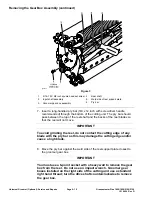
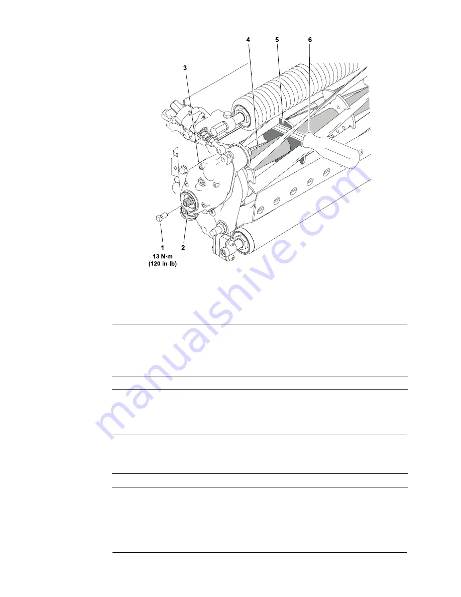
g323373
Figure 3
1.
5/16–18 X 5/8 inch square head set screw 4.
Reel shaft
2.
Input shaft assembly
5.
Weld side of reel support plate
3.
Groomer gear box assembly
6.
Pry bar
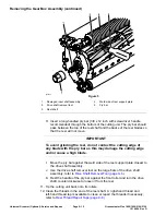
7. Insert a long-handled pry bar (3/8 x 12 inch with screwdriver handle
recommended) through the bottom of the cutting unit. The pry bar should
pass between the top of the reel shaft and the backs of the reel blades so
that the reel will not move.
IMPORTANT
To avoid grinding the reel, do not contact the cutting edge of any
blade with the pry bar as this may damage the cutting edge and/or
cause a high blade.
8. Move the pry bar against the weld side of the reel support plate closest to
the groomer gear box.
IMPORTANT
You must use a 6-point socket with a heavy wall to remove the gear
box from the reel. Do not use an impact wrench. Groomer gear
boxes installed on the right side of the cutting unit use a standard
right hand thread; turn the drive shaft counterclockwise to remove
the gear box.
Universal Groomer (Optional): Service and Repairs
Page 9–10
Greensmaster Flex 1800/1820/2100/2120
12188SL Rev D
Summary of Contents for Greensmaster Flex 1820
Page 4: ...NOTES _...
Page 6: ...Greensmaster Flex 1800 1820 2100 2120 This page is intentionally blank...
Page 8: ...Greensmaster Flex 1800 1820 2100 2120 This page is intentionally blank...
Page 20: ...Greensmaster Flex 1800 1820 2100 2120 Page 3 2 Engine This page is intentionally blank...
Page 30: ...Greensmaster Flex 1800 1820 2100 2120 Page 3 12 Engine This page is intentionally blank...
Page 148: ...Greensmaster Flex 1800 1820 2100 2120 Page 7 30 Cutting Unit This page is intentionally blank...


