Removing the Idler Assembly (continued)
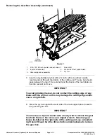
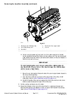
5. Inspect the shields, bearing, and bushing in the idler assembly. Remove and
discard the components that are worn or damaged.
Installing the Idler Assembly
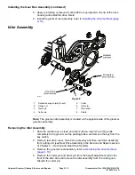
1. If the shields, bearing, or bushing was removed from the idler arm, install
new components as follows:
A. Press the bushing into a groomer plate until the bushing is centered in
the idler arm bore.
B. Press the bearing into the idler arm so that the bearing contacts the
shoulder in idler arm bore and install the bearing retaining ring.
C. Install the bearing shields with flocked side of shield toward the bearing.
D. Check the idler arm orientation and insert the stub shaft through shields
and bearing. Use the through hole in the shaft to prevent shaft from
rotating, tighten the flange nut to
37 to 45 N∙m (27 to 33 ft-lb)
.
E. If the collar was removed from the idler arm, install the collar and tighten
to
33 to 41 N∙m (24 to 30 ft-lb)
.
2. Apply anti-seize lubricant to the inside diameter of the idler arm.
3. Install a new cotter pin and clevis pin and secure the height adjustment rod
to the front of the idler arm.
4. Install reel drive assembly, reel pulley, reel drive belt and then reel drive
cover to left side of cutting unit (see Reel Drive Assembly in the Service and
Repairs section of Chapter 4 - Traction and Reel Drive System).
Greensmaster Flex 1800/1820/2100/2120
Page 9–17
Universal Groomer (Optional): Service and Repairs
12188SL Rev D
Summary of Contents for Greensmaster Flex 1820
Page 4: ...NOTES _...
Page 6: ...Greensmaster Flex 1800 1820 2100 2120 This page is intentionally blank...
Page 8: ...Greensmaster Flex 1800 1820 2100 2120 This page is intentionally blank...
Page 20: ...Greensmaster Flex 1800 1820 2100 2120 Page 3 2 Engine This page is intentionally blank...
Page 30: ...Greensmaster Flex 1800 1820 2100 2120 Page 3 12 Engine This page is intentionally blank...
Page 148: ...Greensmaster Flex 1800 1820 2100 2120 Page 7 30 Cutting Unit This page is intentionally blank...

