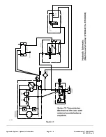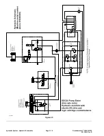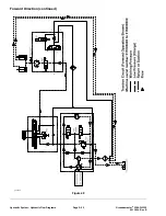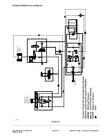
Traction Circuit (Machine Serial Number above 316000000)
The hydraulic traction circuit is a closed loop system consisting of a variable
displacement hydraulic pump and a hydraulic drive axle motor. The hydraulic
pump is driven by a drive shaft connected to the engine crankshaft.
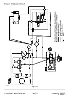
Forward Direction
Pressing the top of traction pedal, angles the hydraulic pump swash plate
to create a flow of fluid. This fluid flow is directed to the hydraulic motor via
hydraulic hoses and tubes which turns the front axle input shaft to drive the front
wheels in the forward direction. The forward traction pressure is limited to 32,495
kPa (4,713 psi) by the forward traction relief valve located in the hydraulic pump.
The fluid flowing from the motor returns to the variable displacement pump and
is continuously pumped through the closed loop traction circuit as long as the
traction pedal is pressed.
The angle of the swash plate determines the stroke of the pump pistons and
therefore the pump flow and ultimately traction speed. When the traction pedal is
pressed a small amount, the swash plate angle is slight resulting in low pump
output and lower traction speed. When the traction pedal is pressed fully, the
pump swash plate angle is dramatic providing maximum pump output and
maximum traction speed.
The hydraulic pump is equipped with a case drain to allow normal internal
leakage to be removed from the pump. The case drain is connected to the
transaxle reservoir.
The hydraulic pump includes a gerotor charge pump. The charge pump provides
a constant supply of charge fluid to the closed loop traction circuit for lubrication
and to make up for fluid that is lost due to internal leakage in the hydraulic pump
and motor. The charge pump takes its suction through a filter from the hydraulic
reservoir (front axle). The charge pump flow is directed to the low pressure side
of the closed loop traction circuit. The charge pressure is limited to 503 kPa
(73 psi) by the charge pressure relief valve in the hydraulic pump. The charge
pump flow in excess of traction circuit charge needs provides hydraulic flow for
the steering and lift circuits.
Hydraulic System: Hydraulic Flow Diagrams
Page 5–24
Groundsmaster
®
3280-D/3320
05138SL Rev B
Summary of Contents for Groundsmaster 3280-D
Page 4: ...NOTES Revision History Page 4 Groundsmaster 3280 D 3320 05138SL Rev B ...
Page 10: ...Preface Page 10 Groundsmaster 3280 D 3320 05138SL Rev B ...
Page 56: ...Gasoline Engine Service and Repairs Page 3 22 Groundsmaster 3280 D 3320 05138SL Rev B ...
Page 84: ...Diesel Engine Service and Repairs Page 4 28 Groundsmaster 3280 D 3320 05138SL Rev B ...
Page 228: ...Hydraulic System Service and Repairs Page 5 144 Groundsmaster 3280 D 3320 05138SL Rev B ...
Page 430: ...PTO System Service and Repairs Page 9 12 Groundsmaster 3280 D 3320 05138SL Rev B ...
Page 466: ...Operator Cab Service and Repairs Page 11 16 Groundsmaster 3280 D 3320 05138SL Rev B ...
Page 470: ...Foldout Drawings Page A 4 Groundsmaster 3280 D 3320 05138SL Rev B ...
Page 508: ......

