Testing the Traction Neutral Sensor (continued)
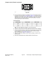
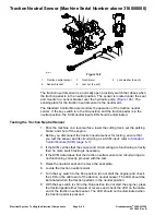
9. If the traction neutral sensor LED did not function correctly, do the following:
A. Ensure that the traction neutral sensor is correctly adjusted; refer to
adjusting the traction neutral sensor.
B. Ensure that the key switch is in the O
FF
position and disconnect the
traction neutral sensor connector from the machine wire harness.
C. Use a multimeter, check that the machine wire harness connector
terminal for the black wire is closed (continuity) to the ground.
D. Turn the key switch to the R
UN
position (do not start the engine) and
check with a multimeter that the machine wire harness connector terminal
for pink wire has system voltage (12 VDC) present.
E. If the black wire is closed to the ground, the pink wire has system voltage
present, and the sensor LED did not function, replace the traction neutral
sensor. Adjust the sensor after installation; refer to
Neutral Sensor (page 6–17)
.
10. After you complete the brake sensor testing, ensure that the sensor
connector is plugged into the machine wire harness.
11. Install the seat plate and lower the operator seat.
Groundsmaster
®
3280-D/3320
Page 6–49
Electrical System: Testing the Electrical Components
05138SL Rev B
Summary of Contents for Groundsmaster 3280-D
Page 4: ...NOTES Revision History Page 4 Groundsmaster 3280 D 3320 05138SL Rev B ...
Page 10: ...Preface Page 10 Groundsmaster 3280 D 3320 05138SL Rev B ...
Page 56: ...Gasoline Engine Service and Repairs Page 3 22 Groundsmaster 3280 D 3320 05138SL Rev B ...
Page 84: ...Diesel Engine Service and Repairs Page 4 28 Groundsmaster 3280 D 3320 05138SL Rev B ...
Page 228: ...Hydraulic System Service and Repairs Page 5 144 Groundsmaster 3280 D 3320 05138SL Rev B ...
Page 430: ...PTO System Service and Repairs Page 9 12 Groundsmaster 3280 D 3320 05138SL Rev B ...
Page 466: ...Operator Cab Service and Repairs Page 11 16 Groundsmaster 3280 D 3320 05138SL Rev B ...
Page 470: ...Foldout Drawings Page A 4 Groundsmaster 3280 D 3320 05138SL Rev B ...
Page 508: ......

