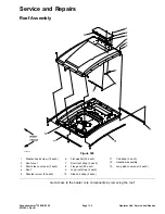
Blade Spindle
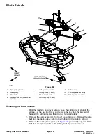
g223993
Figure 296
1.
Idler pulley (2 each)
5.
Left spindle assembly
9.
Cutting deck
2.
Drive pulley
6.
Cutting blade (3 each)
10.
Center spindle assembly
3.
Drive belt
7.
Blade bolt (3 each)
11.
Right spindle assembly
4.
Ribbed neck bolt (8 each per
spindle)
8.
Anti-scalp cup (3 each)
Removing the Blade Spindle
1. Park the machine on a level surface, raise the cutting deck, shut off the
engine, set the parking brake, and remove the key from the key switch.
Support the cutting deck so that it cannot fall accidentally.
2. Remove the belt covers from the top of the cutting deck. Remove the drive
belt from the deck pulleys; refer to the
Cutting Unit Operator’s Manual
.
3. Remove the cutting blade (item 6 in
), anti-scalp cup, and blade
bolt from the spindle; refer to the
Cutting Unit Operator’s Manual
.
Cutting Units: Service and Repairs
Page 10–8
Groundsmaster
®
3280-D/3320
05138SL Rev B
Summary of Contents for Groundsmaster 3280-D
Page 4: ...NOTES Revision History Page 4 Groundsmaster 3280 D 3320 05138SL Rev B ...
Page 10: ...Preface Page 10 Groundsmaster 3280 D 3320 05138SL Rev B ...
Page 56: ...Gasoline Engine Service and Repairs Page 3 22 Groundsmaster 3280 D 3320 05138SL Rev B ...
Page 84: ...Diesel Engine Service and Repairs Page 4 28 Groundsmaster 3280 D 3320 05138SL Rev B ...
Page 228: ...Hydraulic System Service and Repairs Page 5 144 Groundsmaster 3280 D 3320 05138SL Rev B ...
Page 430: ...PTO System Service and Repairs Page 9 12 Groundsmaster 3280 D 3320 05138SL Rev B ...
Page 466: ...Operator Cab Service and Repairs Page 11 16 Groundsmaster 3280 D 3320 05138SL Rev B ...
Page 470: ...Foldout Drawings Page A 4 Groundsmaster 3280 D 3320 05138SL Rev B ...
Page 508: ......

