Setting Up the Center Cutting Unit
Note:
It is best to use the Toro tool (Part No.
121-3874) to tighten the tensioning cap.
1.
Rotate the blade on each spindle until the ends
face forward and backward.
2.
Measure from the floor to the front tip of the
cutting edge.
3.
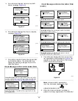
Adjust the shims (3 mm or 1/8 inch) on the front
caster fork(s) to match the height-of-cut decal
(
); refer to
(page 29)
.
g008866
Figure 35
1.
Tensioning cap
4.
Top axle-mounting hole
2.
Spacers
5.
Caster wheel
3.
Shims
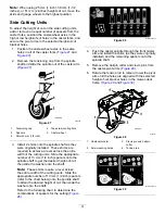
Setting Up the Side Cutting Units
1.
Rotate the blade of each spindle until the ends
face forward and backward.
2.
Measure from the floor to the front tip of the
cutting edge.
3.
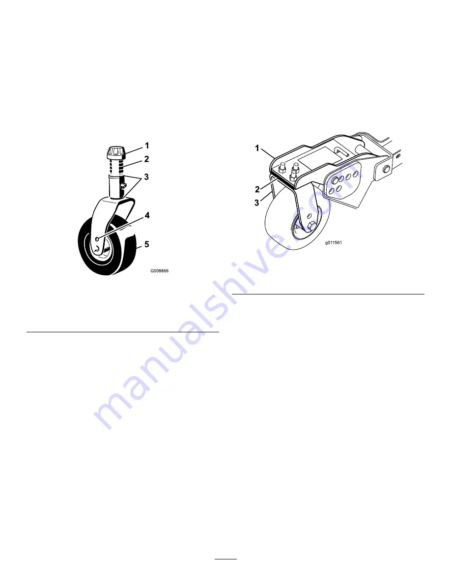
Adjust the shims (3 mm or 1/8 inch) on front
caster arm(s) to match the height-of-cut decal
(
).
Note:
For the outside blade spindle only, refer
to
Adjusting the Height of Cut (page 29)
.
g011561
Figure 36
1.
Front caster arm
3.
Front caster fork
2.
Shims
Matching the Height of Cut
Between Cutting Units
1.
Position the blade side to side on the outside
spindle of both side cutting units.
Note:
Measure from the floor to the tip of the
cutting edge on both units and compare. These
numbers should be within 3 mm (1/8 inch) of
each other. Make no adjustment at this time.
2.
Position the blade side to side on the inside
spindle of the side cutting unit and corresponding
outside spindle of the front cutting unit.
Note:
Measure from the floor to the tip of the
cutting edge on the inside edge of side cutting
unit to the corresponding outside edge of front
cutting unit and compare. The side mower-deck
measurement should be within 3 mm (1/8 inch)
of the front cutting unit.
Note:
All 3 cutting unit caster wheels should
remain on the ground with counterbalance
applied.
Note:
If adjustments need to be made to match
the cut between the front and side cutting units,
34
Summary of Contents for Groundsmaster 4000
Page 85: ...Notes ...

