background image

Passive regeneration occurs continuously while
the engine is running—run the engine at full
engine speed when possible to promote DPF
regeneration.

If the back pressure in the DPF is too high or a
reset regeneration has not occurred for 100 hours,
the engine computer signals you through the
InfoCenter when reset regeneration is running.

Allow the reset regeneration process to complete
before shutting off the engine.

Operate and maintain your machine with the function
of the DPF in mind. Engine load at high idle (full
throttle) engine speed generally produces adequate
exhaust temperature for DPF regeneration.

Important:

Minimize the amount of time that you

idle the engine or operate the engine at low-engine

speed to help reduce the accumulation of soot in
the soot filter.

DPF Soot Accumulation

Over time, the diesel particulate filter accumulates
soot in the soot filter. The computer for the engine
monitors the soot level in the DPF.

When enough soot accumulates, the computer
informs you that it is time to regenerate the DPF.

DPF regeneration is a process that heats the DPF
to convert the soot to ash.

In addition to the warning messages, the computer
reduces the power produced by the engine at
different soot-accumulation levels.

Engine Warning Messages—Soot Accumulation

Indication Level

Fault Code

Engine Power Rating

Recommended Action

Level 1: Engine

Warning

g213866

Figure 38

Check Engine

SPN 3719, FMI 16

The computer de-rates the

engine power to 85%.

Perform a parked regeneration

as soon as possible; refer

to

Performing a Parked

or Recovery Regeneration

(page 47)

.

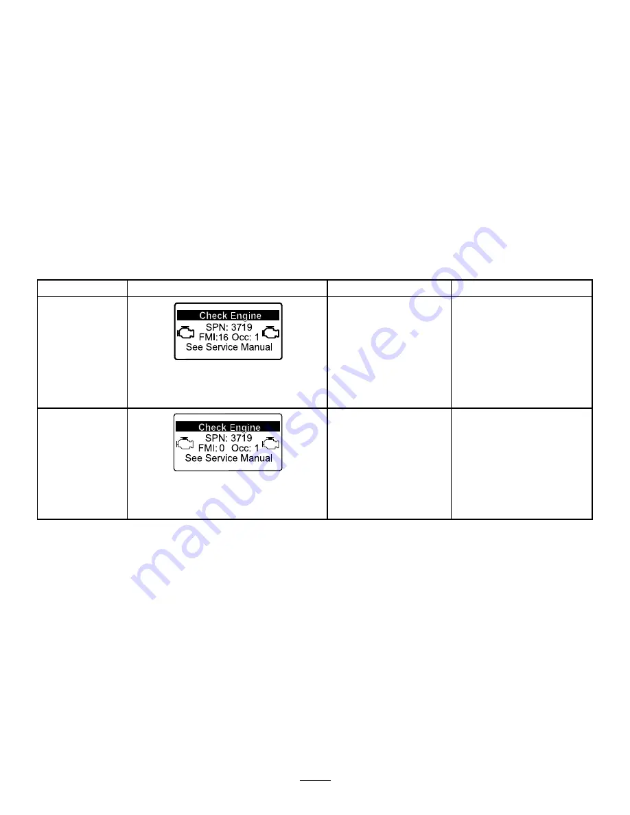
Level 2: Engine

Warning

g213867

Figure 39

Check Engine

SPN 3719, FMI 0

The computer de-rates the

engine power to 50%.

Perform a recovery regeneration

as soon as possible; refer to

Performing a Parked or

Recovery Regeneration

(page 47)

.

39


Summary of Contents for Groundsmaster 4000

Page 1: ...m No 3428 799 Rev A Groundsmaster 4000 or 4010 Rotary Mower Model No 30609 Serial No 403450001 and Up Model No 30636 Serial No 403450001 and Up Register at www Toro com Original Instructions EN 3428 799 A ...

Page 2: ...owing grass on well maintained lawns in parks golf courses sports fields and on commercial grounds Using this product for purposes other than its intended use could prove dangerous to you and bystanders Read this information carefully to learn how to operate and maintain your product properly and to avoid injury and product damage You are responsible for operating the product properly and safely V...

Page 3: ...General Safety 53 Pushing or Towing the Machine 53 Locating the Jacking Points 54 Hauling the Machine 54 Locating the Tie Down Points 54 Maintenance 55 Maintenance Safety 55 Recommended Maintenance Schedule s 55 Daily Maintenance Checklist 57 Pre Maintenance Procedures 58 Removing the Hood 58 Lubrication 58 Greasing the Bearings and Bushings 58 Engine Maintenance 61 Engine Safety 61 Servicing the ...

Page 4: ...y activity that causes distractions otherwise injury or property damage may occur Do not operate the machine without all guards and other safety protective devices in place and functioning properly on the machine Keep your hands and feet away from rotating parts Keep clear of the discharge opening Keep bystanders and children out of the operating area Never allow children to operate the machine Sh...

Page 5: ... 3 Caustic liquid chemical burn hazard 8 Battery acid can cause blindness or severe burns 4 Wear eye protection 9 Flush eyes immediately with water and get medical help fast 5 Read the Operator s Manual 10 Contains lead do not discard decal93 7272 93 7272 1 Cutting dismemberment hazard fan stay away from moving parts decal93 7818 93 7818 1 Warning read the Operator s Manual for instructions on tor...

Page 6: ...ving parts decal104 3578 104 3578 1 Height of cut adjustment decal104 3579 104 3579 1 Low height of cut adjustment 2 High height of cut adjustment decal106 6754 106 6754 1 Warning do not touch the hot surface 2 Cutting dismemberment hazard fan entanglement hazard belt stay away from moving parts decal106 6755 106 6755 1 Engine coolant under pressure 3 Warning do not touch the hot surface 2 Explosi...

Page 7: ...slow 2 Disengage the deck 3 Lock the parking brake 4 Wait 5 minutes 5 Turn the key to shut off the engine 6 Remove the key from the switch 3 Read the Operator s Manual 4 Pull the knob out to engage the PTO 5 Push the knob in to disengage the PTO 6 Raise the decks to go to H range decal114 0849 114 0849 1 Warning 1 Disengage the PTO 2 Raise the deck 4 Forward direction 2 Do not place your foot here...

Page 8: ...le speed adjustment 13 Lower center deck 7 Slow 14 Lower right deck decal120 6604 120 6604 1 Thrown object hazard keep bystanders away from the machine 2 Cutting dismemberment hazard of hand mower blade stay away from moving parts keep all guards and shields in place 3 Cutting dismemberment hazard of foot mower blade stay away from moving parts keep all guards and shields in place 8 ...

Page 9: ...3 There is rollover protection when the roll bar is up 6 Drive slowly when turning decal121 1599 121 1599 1 Read the Operator s Manual for information on fuses decal121 3884 121 3884 1 Engine stop 3 Engine start 2 Engine preheat decal121 3887 121 3887 1 Read the Operator s Manual decal125 9688 125 9688 Model with Cab Only 1 Windshield wipers off 3 Windshield wipers on 2 Windshield wipers 4 Spray w...

Page 10: ...0 0594 1 Warning read the Operator s Manual when sitting in the cab always wear a seat belt wear hearing protection decal130 0611 130 0611 Model with Cab Only 1 Warning 1 Remove the pin 2 Raise the doors 3 Exit the cab decal130 5355 130 5355 1 Close the rear window 2 Raise the hood decal130 5356 130 5356 1 Use the foot pedal to move forward or in reverse 10 ...

Page 11: ... hazard of hand or foot stay away from moving parts keep all guards and shields in place 7 Tipping hazard lower the cutting unit when driving down slopes slow the machine before turning do not turn at high speeds 8 Warning engage the parking brake shut off the engine and remove the key before leaving the machine decal121 8378 121 8378 Model with Cab Only 1 Fan off 3 Cold air 5 External air 7 Air c...

Page 12: ...ator s Manual decal132 3600 132 3600 Model with Cab Only 1 Read the Operator s Manual for more information on fuses 5 Working light 20 A 2 Headlight 25 A 6 Auxiliary power 15 A 3 Condenser fan and A C clutch 30 A 7 Cab light 15 A 4 Fan 25 A 8 Windshield wipers 15 A decal133 5618 133 5618 12 ...

Page 13: ...perator s Manual for information on fuses 7 Infocenter 2 A 2 Engine preheat 60 A 8 Headlights 15 A 3 Power supply 7 5 A 9 Power seat 10 A 4 Turn signals 10 A 10 Lighter 10 A 5 Engine control unit 10 A 11 Horn 10 A 6 System power 10 A 13 ...

Page 14: ... Use to reference engine information Declaration of Conformity 1 Note Determine the left and right sides of the machine from the normal operating position 1 Greasing the Machine No Parts Required Procedure Grease the machine before use refer to Lubrication page 58 Important Failure to properly grease the machine will result in premature failure of critical parts 2 Checking the Tire Pressure No Par...

Page 15: ...y gear drive oil refer to Checking the Planetary Gear Drive Oil page 27 5 Check the rear axle lubricant refer to Checking the Rear Axle Lubricant page 28 6 Check the rear axle gearbox lubricant refer to Checking the Rear Axle Gearbox Lubricant page 28 4 Installing the Decal CE Machines Only Parts needed for this procedure 1 Production year decal Procedure On machines requiring CE compliance instal...

Page 16: ... the locking latch push down on both pedals and pull the parking brake latch out To release the parking brake press both pedals until the parking brake latch retracts Key Switch The key switch Figure 5 has 3 positions OFF ON PREHEAT and START g028453 Figure 5 1 Lift switches 5 High Low speed control 2 PTO switch 6 Engine speed switch 3 Key switch 7 Light switch optional 4 InfoCenter Engine Speed S...

Page 17: ...tion g028454 Figure 6 1 Power point switch 2 Cruise control switch Power Point Port Use the power point port to power optional electrical accessories Figure 6 Seat Adjustments Seat Adjustment Lever Move the seat adjustment lever on the side of the seat outward slide the seat to the desired position and release the lever to lock the seat into position Figure 7 g008837 Figure 7 1 Weight gauge 4 Seat...

Page 18: ... temperature control knob to regulate the air temperature in the cab Figure 8 Windshield Wiper Switch Use this switch to turn the windshield wipers on or off Figure 8 Air Conditioning Switch Use this switch to turn the air conditioning on or off Figure 8 Windshield Latch Lift up the latches to open the windshield Figure 9 Press in the latch to lock windshield to the OPEN position Pull out and down...

Page 19: ... to open a menu where a right arrow indicates additional content Beeper activated when lowering the decks or for advisories and faults Note The purpose of each button may change depending on what is required at the time Each button is labeled with an icon displaying its current function InfoCenter Icon Description SERVICE DUE Indicates when scheduled service should be performed Engine rpm status i...

Page 20: ...les are shown below Operator should put the machine in neutral Engine start denied Engine shutdown Engine coolant is too hot Hydraulic fluid is too hot Sit down or engage the parking brake DPF ash accumulation notification Refer to Servicing the Diesel Particulate Filter DPF in the maintenance section for details Reset standby regeneration request Parked or recovery regeneration request A parked o...

Page 21: ... high temp and fan on Settings Menu Item Description Units Controls the units used on the InfoCenter the menu choices are English or Metric Language Controls the language used on the InfoCenter LCD Backlight Controls the brightness of the LCD display LCD Contrast Controls the contrast of the LCD display Protected Menus Allows a person authorized by your company with the PIN code to access protecte...

Page 22: ...tion Use the right button to change the setting Setting the Protect Settings to OFF allows you to view and change the settings in the Protected Menu without entering the PIN code Setting the Protect Settings to ON hides the protected options and requires you to enter the PIN code to change the setting in the Protected Menu After you set the PIN code rotate the key switch OFF and back to the ON pos...

Page 23: ...Specifications Note Specifications and design are subject to change without notice g278707 Figure 13 23 ...

Page 24: ...rized Service Dealer or authorized Toro distributor or go to www Toro com for a list of all approved attachments and accessories To ensure optimum performance and continued safety certification of the machine use only genuine Toro replacement parts and accessories Replacement parts and accessories made by other manufacturers could be dangerous and such use could void the product warranty Operation...

Page 25: ...reating any source of ignition until the fuel vapors have dissipated Checking the Engine Oil Level Before you start the engine and use the machine check the oil level in the engine crankcase refer to Checking the Engine Oil Level page 61 Checking the Cooling System Before you start the engine and use the machine check the cooling system refer to Checking the Cooling System page 25 Checking the Hyd...

Page 26: ... This machine can also use a biodiesel blended fuel of up to B20 20 biodiesel 80 petrodiesel Sulfur content Ultra low sulfur 15 ppm Biodiesel fuel specification ASTM D6751 or EN14214 Blended fuel specification ASTM D975 EN590 or JIS K2204 Important The petroleum diesel portion must be ultra low sulfur Observe the following precautions Biodiesel blends may damage painted surfaces Use B5 biodiesel c...

Page 27: ...e Torque of the Wheel Lug Nuts Service Interval After the first hour After the first 10 hours Every 200 hours Torque the wheel lug nuts to 115 to 136 N m 85 to 100 ft lb in the order shown in Figure 16 and Figure 17 g033358 Figure 16 Front Wheels g033359 Figure 17 Rear Wheels WARNING Failing to maintain proper torque of the wheel lug nuts could result in personal injury Torque the wheel lug nuts t...

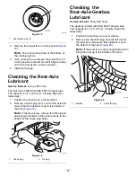
Page 28: ... from 1 end of the axle and ensure that the lubricant is up to the bottom of the hole Figure 19 Note If the level is low remove the fill plug and add enough lubricant to bring the level up to the bottom of the check plug holes g011487 Figure 19 1 Check plug 2 Fill plug Checking the Rear Axle Gearbox Lubricant Service Interval Every 400 hours The gearbox is filled with SAE 85W 140 gear lube The cap...

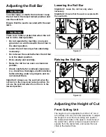
Page 29: ...s doorways electrical wires before driving under any objects and do not contact them Important Always use the seat belt when the roll bar is in the raised and locked position Do not use the seat belt when the roll bar is in the lowered position Lowering the Roll Bar Important Lower the roll bar only when necessary Important Ensure that the seat is secured with the seat latch g221650 Figure 21 Rais...

Page 30: ...he caster arm Figure 23 6 Install 2 shims onto the spindle shaft as they were originally installed Note These shims require a level across the entire width of the cutting units Slide the appropriate number of 13 mm 1 2 inch spacers refer to the chart below onto the spindle shaft to attain the desired height of cut then slide the washer onto the shaft Refer to the following chart to determine the c...

Page 31: ... the cutting units Slide the appropriate number of 13 mm 1 2 inch spacers onto the spindle shaft to get the desired height of cut then slide the washer onto the shaft Note These shims require a level across the entire width of the cutting units Slide the appropriate number of 13 mm 1 2 inch spacers refer to the chart below onto the spindle shaft to attain the desired height of cut then slide the w...

Page 32: ...eight of cut bracket holes in the mower deck frame insert the clevis pins and install the hairpin cotters Figure 32 decal100 5694nc Figure 32 Adjusting the Skids Mount the skids in the lower position when operating at heights of cut greater than 64 mm 2 1 2 inches and in the higher position when operating at heights of cut lower than 64 mm 2 1 2 inches Note When the skids become worn you can switc...

Page 33: ...2 to 207 kPa 25 to 30 psi 3 Check and adjust the air pressure in all of the caster tires for the cutting unit to 345 kPa 50 psi 4 Check the charge and counterbalance pressures with the engine at HIGH IDLE using hydraulic test ports Note Adjust the counterbalance to 2241 kPa 325 psi 5 Check for bent blades refer to Checking for a Bent Blade page 79 6 Cut grass in a test area to determine if all cut...

Page 34: ...only refer to Adjusting the Height of Cut page 29 g011561 Figure 36 1 Front caster arm 3 Front caster fork 2 Shims Matching the Height of Cut Between Cutting Units 1 Position the blade side to side on the outside spindle of both side cutting units Note Measure from the floor to the tip of the cutting edge on both units and compare These numbers should be within 3 mm 1 8 inch of each other Make no ...

Page 35: ...Before each use or daily The machine has interlock switches in the electrical system These switches disengage either the traction unit or the PTO whenever you leave the seat If you disengage the PTO and engage the parking brake before you leave the seat the engine continues to run 1 Drive the machine slowly to a large open area Lower the cutting unit shut off the engine and apply the parking brake...

Page 36: ... Before you start the engine ensure that all drives are in neutral the parking brake is engaged and you are in the operating position Do not carry passengers on the machine and keep bystanders and children out of the operating area Operate the machine only in good visibility to avoid holes or hidden hazards Avoid mowing on wet grass Reduced traction could cause the machine to slide Keep your hands...

Page 37: ... for operating the machine on slopes and to determine whether you can operate the machine in the conditions on that day and at that site Changes in the terrain can result in a change in slope operation for the machine Avoid starting stopping or turning the machine on slopes Avoid making sudden changes in speed or direction Make turns slowly and gradually Do not operate a machine under any conditio...

Page 38: ... fluid or coolant reaches a certain temperature a reverse fan cycle is automatically initiated This cycle blows debris off the rear screen and lowers the engine coolant and hydraulic fluid temperatures You can complete a manually initiated reverse cycle by simultaneously pressing the right and left buttons on the InfoCenter It is recommended that you manually reverse the fan before you leave the w...

Page 39: ...er time the diesel particulate filter accumulates soot in the soot filter The computer for the engine monitors the soot level in the DPF When enough soot accumulates the computer informs you that it is time to regenerate the DPF DPF regeneration is a process that heats the DPF to convert the soot to ash In addition to the warning messages the computer reduces the power produced by the engine at di...

Page 40: ...ent ash accumulation levels InfoCenter Advisory and Engine Warning Messages Ash Accumulation Indication Level Fault Code Engine Speed Reduction Engine Power Rating Recommended Action Level 1 Engine Warning g213863 Figure 40 Check Engine SPN 3720 FMI 16 None The computer de rates the engine power to 85 Service the DPF refer to Servicing the Diesel Oxidation Catalyst DOC and the Soot Filter page 63 ...

Page 41: ...level When the high exhaust temperature icon is displayed in the InfoCenter a regeneration is in progress During reset regeneration the engine computer adjusts the engine settings to raise the exhaust temperature Reset Refer to Reset Regeneration page 44 Types of diesel particulate filter regeneration that require you to park the machine Type of Regeneration Conditions that cause DPF regeneration ...

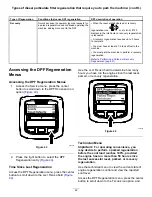
Page 42: ... Regeneration Menus 1 Access the Service menu press the center button to scroll down to the DPF REGENERATION option Figure 43 g227667 Figure 43 2 Press the right button to select the DPF Regeneration entry Figure 43 Time Since Last Regeneration Access the DPF Regeneration menu press the center button to scroll down to the LAST REGEN field Figure 44 Use the LAST REGEN field to determine how many ho...

Page 43: ... parked regeneration request and the engine computer is processing the regeneration Recov Stby The engine computer is requesting that you run a recovery regeneration Recov Regen You initiated a recovery regeneration request and the engine computer is processing the regeneration View the soot load which is measured as the percentage of soot in the DPF Figure 47 refer to the soot load table Note The...

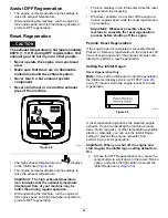
Page 44: ...ile the reset regeneration is processing Whenever possible do not shut off the engine or reduce engine speed while the reset regeneration is processing Important Whenever possible allow the machine to complete the reset regeneration process before shutting off the engine Periodic Reset Regeneration If the engine has not completed a successful Reset Parked or Recovery regeneration in the previous 1...

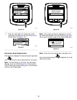
Page 45: ...s Note If INHIBIT REGEN is set to ON the InfoCenter displays ADVISORY 185 Figure 52 Press button 3 to set inhibit regeneration setting to OFF and continue with the reset regeneration g224394 Figure 52 Note If the engine exhaust temperature is too low the InfoCenter displays ADVISORY 186 Figure 53 to inform you to set the engine to full throttle high idle g224395 Figure 53 Note When the reset regen...

Page 46: ...Advisory 188 displays every 15 minutes g224397 Figure 56 If you do not perform a parked regeneration within 2 hours the InfoCenter displays parked regeneration required power takeoff disabled ADVISORY 189 Figure 57 g224398 Figure 57 Important Perform a parked regeneration to restore the PTO function refer to Preparing to Perform a Parked or Recovery Regeneration page 47 and Performing a Parked or ...

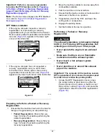
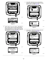
Page 47: ... performing the parked regeneration Recovery Regeneration Ensure that you have 1 2 tank of fuel before performing the recovery regeneration 2 Move the machine outside to an area away from combustible materials 3 Park the machine on a level surface 4 Ensure that the traction control or motion control levers are in the NEUTRAL position 5 If applicable shut off the PTO and lower the cutting units or ...

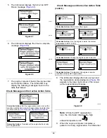
Page 48: ...e performing the recovery regeneration and press the right button to continue Figure 64 g224414 g227678 Figure 64 3 At the DPF checklist screen verify that the parking brake is engaged and that the engine speed is set to low idle Figure 65 g224407 g227679 Figure 65 4 At the INITIATE DPF REGEN screen press the right button to continue Figure 66 g224626 g224630 Figure 66 48 ...

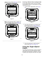
Page 49: ...orrective Action Troubleshoot the engine fault and retry DPF regeneration Check Message and Corrective Action Table cont d Corrective Action Start and run the engine Corrective Action Run the engine to warm the coolant temperature to 60 C 140 F Corrective Action Change the engine speed to low idle Corrective Action Troubleshoot the engine computer condition and retry DPF regeneration 8 The InfoCen...

Page 50: ...cel a running parked or recovery regeneration process 1 Access the DPF Regeneration menu Figure 72 g227305 Figure 72 2 Press the center button to scroll down to the PARKED REGEN CANCEL Figure 72 or the RECOVERY REGEN CANCEL option Figure 73 g227306 Figure 73 3 Press the right button to select the Regen Cancel entry Figure 72 or Figure 73 Using the Engine Speed Switch The engine speed switch has 2 ...

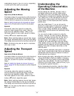
Page 51: ...eature in conjunction with cruise control Understanding the Operating Characteristics of the Machine Practice driving the machine because it has a hydrostatic transmission and its characteristics may differ from other turf maintenance machines Some points to consider when operating the traction unit cutting unit or other implements are that the transmission engine speed and the load on the mower b...

Page 52: ... most turf conditions Decreasing the counterbalance setting can produce a more stable cutting unit but can decrease the traction capability Increasing the counterbalance setting can increase the traction capability but may result in a poor after cut appearance Refer to the machine Service Manual for your traction unit for instructions to adjust the counterbalance pressure Resolving After Cut Appea...

Page 53: ...icing cleaning or storing it Clean grass and debris from the cutting units mufflers and engine compartment to help prevent fires Clean up oil or fuel spills If the cutting units are in the transport position use the positive mechanical lock if available before you leave the machine unattended Allow the engine to cool before storing the machine in any enclosure Remove the key and shut off the fuel ...

Page 54: ...ront tire The hose assembly includes 1 hose Part No 95 8843 2 coupler fittings Part No 95 0985 and 2 hydraulic fittings Part No 340 77 Locating the Jacking Points DANGER Mechanical or hydraulic jacks may fail to support machine and cause a serious injury Use jack stands when supporting the machine Do not use hydraulic jacks There are jacking points located at the front and rear of the machine On t...

Page 55: ...e optimal performance of the machine use only genuine Toro replacement parts Replacement parts made by other manufacturers could be dangerous and such use could void the product warranty Recommended Maintenance Schedule s Maintenance Service Interval Maintenance Procedure After the first hour Torque the wheel lug nuts After the first 10 hours Torque the wheel lug nuts Check the alternator belt ten...

Page 56: ...alternative fluid change the hydraulic fluid If you are not using the recommended hydraulic fluid or have ever filled the reservoir with an alternative fluid replace the hydraulic filter sooner if the service interval indicator is in the red zone Inspect the side cutting unit damper Inspect the cutting unit caster wheel assemblies Every 1 000 hours Drain and clean the fuel tank If you are using th...

Page 57: ...nusual operating noises Check the hydraulic system oil level Check the hydraulic hoses for damage Check for fluid leaks Check the fuel level Check the tire pressure Check the instrument operation Check the height of cut adjustment Lubricate all the grease fittings 2 Clean the machine Touch up any damaged paint 1Check the glow plug and injector nozzles if starting is hard there is excess smoke or r...

Page 58: ... Service Interval Every 50 hours Lubricate all of the bearings and bushings Every 500 hours Yearly whichever comes first The machine has grease fittings that you must lubricate regularly with No 2 lithium grease Also lubricate the machine immediately after every washing The grease fitting locations and quantities are Traction Unit 2 front and rear axle pivot bushings Figure 78 2 steering cylinder ...

Page 59: ...ngs Figure 81 g011557 Figure 80 g017810 Figure 81 Front Lift Assemblies 2 each side lift arm cylinder bushings Figure 82 2 lift arm ball joints Figure 83 g020455 Figure 82 g011551 Figure 83 Side Cutting Unit 1 caster fork shaft bushing Figure 84 2 each side spindle shaft bearings located under the pulley 1 idler arm pivot bushings located on the idler arm 59 ...

Page 60: ...mblies 6 main lift arm bushings Figure 85 and Figure 86 2 bell crank pivot bushings Figure 87 4 rear arm bushings Figure 87 4 lift cylinder bushings Figure 88 g011552 Figure 85 g011553 Figure 86 g011554 Figure 87 g011555 Figure 88 60 ...

Page 61: ...ly If the engine oil level is above the Full mark on the dipstick the engine oil may be diluted with fuel If the engine oil level is above the Full mark change the engine oil The best time to check the engine oil is when the engine is cool before it has been started for the day If it has already been run allow the oil to drain back down to the sump for at least 10 minutes before checking If the oi...

Page 62: ... 91 requires it Changing the air filter before it is necessary only increases the chance of dirt entering the engine when you remove the filter g009709 Figure 91 1 Air cleaner indicator Important Be sure that the cover is seated correctly and seals with the air cleaner body 1 Replace the air cleaner Figure 92 g031861 Figure 92 Note Do not clean a used element because cleaning it can damage the fil...

Page 63: ...soot filter g213865 Figure 94 If engine faults CHECK ENGINE SPN 3251 FMI 0 CHECK ENGINE SPN 3720 FMI 0 or CHECK ENGINE SPN 3720 FMI 16in the InfoCenter Figure 95 display in the InfoCenter clean the soot filter using the steps that follow g214715 g213864 g213863 Figure 95 1 Refer to the Engine section in the Service Manual for information on disassembling and assembling the diesel oxidation catalys...

Page 64: ...ing the machine for an extended period Use clean fuel to flush out the tank Inspecting the Fuel Lines and Connections Service Interval Every 400 hours Yearly whichever comes first Inspect the fuel lines for deterioration damage or loose connections Servicing the Water Separator Service Interval Before each use or daily Drain water or other contaminants from the fuel filter water separator Every 40...

Page 65: ...rom sparks and flames Unplug the charger before connecting or disconnecting the battery Wear protective clothing and use insulated tools Servicing the Battery Service Interval Every 25 hours Check the electrolyte level If the machine is in storage check it every 30 days Important Before welding on the machine disconnect the negative cable from the battery to prevent damage to the electrical system...

Page 66: ...rsonal injury Always disconnect the negative black battery cable before disconnecting the positive red cable Always connect the positive red battery cable before connecting the negative black cable 3 Coat both battery connections with Grafo 112X skin over grease Toro Part No 505 47 petroleum jelly or light grease to prevent corrosion 4 Slide the rubber boot over the positive terminal 5 Close the b...

Page 67: ...on pedal to the bracket Figure 105 g009745 Figure 105 1 Traction pedal 2 Mounting nuts and bolts 2 Pivot the pedal to the desired operating angle and tighten the nuts Figure 105 Changing the Planetary Gear Drive Oil Service Interval After the first 200 hours Every 800 hours or yearly whichever comes first Use a high quality SAE 85W 140 gear lube 1 With the machine on a level surface position a whe...

Page 68: ...all the plug and move the machine approximately 3 m 10 ft to distribute the oil through the brake system Then remove the plug and add the remaining oil 7 Install the plug 8 Repeat the procedure on the opposite planetary brake assembly Changing the Rear Axle Oil Service Interval After the first 200 hours Every 800 hours 1 Position the machine on a level surface 2 Clean the area around the 3 drain p...

Page 69: ...g a hot radiator and surrounding parts can cause severe burns Always allow the engine to cool at least 15 minutes before removing the radiator cap Use a rag when opening the radiator cap and open the cap slowly to allow steam to escape Do not operate the machine without the covers in place Keep your fingers hands and clothing clear of rotating fan and drive belt Checking the Cooling System Service...

Page 70: ...s not eliminate the need for routine cleaning Periodic cleaning and inspection of the radiator oil cooler is still required 1 Shut off the engine remove the key and raise the hood 2 Clean the engine area thoroughly of all debris 3 Clean both sides of the radiator oil cooler area thoroughly with compressed air Figure 111 Note Start from the fan side and blow the debris out toward the back Then clea...

Page 71: ...e Interval After the first 10 hours Every 100 hours Proper tension of the belt allows 10 mm 3 8 inch of deflection when a force of 44 N m 10 ft lb is applied on the belt midway between the pulleys If the deflection is not 10 mm 3 8 inch loosen the alternator mounting bolts Figure 113 Note Increase or decrease the alternator belt tension and tighten the bolts Check the deflection of the belt again ...

Page 72: ...emoval of the extension spring Figure 114 3 Loosen the flange nut securing the stop bolt to the mounting tab and move the idler pulley away from the belt to release the belt tension Figure 114 Note Loosen the nut enough to allow the idler arm to pass the stop bolt Note If the stop bolt is ever removed from the mounting tab make sure that it is installed again in the hole that aligns the stop bolt ...

Page 73: ...to identify a satisfactory product Note Toro does not assume responsibility for damage caused by improper substitutions so use products only from reputable manufacturers who will stand behind their recommendation High Viscosity Index Low Pour Point Anti wear Hydraulic Fluid ISO VG 46 High Viscosity Index Low Pour Point Anti wear Hydraulic Fluid ISO VG 46 cont d Material Properties Viscosity ASTM D...

Page 74: ...ic fluid refer to Changing the Hydraulic Fluid page 74 Important Use only the hydraulic fluids specified Other fluids damage the system g020456 Figure 117 1 Hydraulic reservoir 5 Install the reservoir cap start the engine and use all the hydraulic controls to distribute hydraulic fluid throughout the system Note Also check for leaks then shut off the engine 6 Check the fluid level and add enough t...

Page 75: ...erioration and chemical deterioration Make all necessary repairs before operating the machine Adjusting the Counterbalance Pressure The counterbalance test port is used to test the pressure in the counterbalance circuit Figure 119 The recommended counterbalance pressure is 2241 kPa 325 psi To adjust the counterbalance pressure loosen the locknut rotate the adjusting screw Figure 119 clockwise to i...

Page 76: ...er the operator s platform 4 Sit on the seat start the engine and lower the cutting unit until it is slightly off the floor 5 Shut off the engine wait for all parts to stop moving and remove the key 6 Secure the height of cut chains to the rear of the cutting unit 7 Pivot the transport latch upward into position and secure it with the clevis pin and cotter pin Adjusting the Cutting Unit Pitch Meas...

Page 77: ... be replaced 1 Raise the cutting unit so the wheels are off the floor and block the cutting unit so it cannot fall 2 Remove the tensioning cap spacer s and thrust washer from the top of the caster spindle 3 Pull the caster spindle out of the mounting tube Note Keep the thrust washer and spacer s on the bottom of the spindle 4 Insert a pin punch into the top or bottom of the mounting tube and drive...

Page 78: ...aring from the wheel hub and allow the bearing spacer to fall out Figure 124 and Figure 125 3 Remove the bearing from the opposite side of the wheel hub 4 Check the bearings spacer and inside of the wheel hub for wear and replace any damaged parts 5 To assemble the caster wheel push the bearing into the wheel hub Note When installing the bearings press on the outer race of the bearing 6 Slide the ...

Page 79: ...s page 79 Removing and Installing the Cutting Unit Blade s Replace the blade if it hits a solid object is out of balance or is bent Always use genuine Toro replacement blades to ensure safety and optimum performance 1 Park the machine on a level surface raise the cutting unit to the highest position engage the parking brake shut off the engine and remove the key Note Block the cutting unit to prev...

Page 80: ...cutting unit the grass appears streaked when it is cut You can correct this problem by ensuring that the blades are straight 1 Park the machine on a level surface 2 Raise the height of cut to the highest position refer to Adjusting the Height of Cut page 29 3 Lower the cutting unit onto the flat surface and remove the covers from the top of the cutting unit 4 Loosen the flange nut that secures the...

Page 81: ...djust the idler pulley and install the belt covers Cab Maintenance Cleaning the Cab Important Use care around the cab seals and lights Figure 130 If you are using a pressure washer keep the washer wand at least 0 6 m 2 ft away from the machine Do not use the pressure washer directly on the cab seals and lights or under the rear overhang g034330 Figure 130 1 Seal 3 Keep wand 0 6 m 2 ft away 2 Light...

Page 82: ...uch as grass and leaves from entering the cab filters 1 Rotate the screen cover down 2 Clean the filter with water Note Do not use a pressure washer Important If the filter has a hole tear or other damage replace the filter 3 Allow the pre filter to dry before installing it into the machine 4 Rotate the filter screen around the tabs until the latch locks into the latch mount assembly Figure 133 g0...

Page 83: ...o clean the machine Preparing the Traction Unit 1 Thoroughly clean the traction unit cutting units and engine 2 Check the tire pressure Inflate all traction unit tires to 83 to 103 kPa 12 to 15 psi 3 Check all fasteners for looseness and tighten them as necessary 4 Grease all grease fittings and pivot points Wipe up any excess lubricant 5 Lightly sand and use touch up paint on painted areas that a...

Page 84: ...y in the switch to the OFF position 6 Thoroughly drain all fuel from the fuel tank lines and the fuel filter water separator assembly 7 Flush the fuel tank with fresh clean diesel fuel 8 Secure all fuel system fittings 9 Thoroughly clean and service the air cleaner assembly 10 Seal the air cleaner inlet and the exhaust outlet with weatherproof tape 11 Check the antifreeze protection and add as nee...

Page 85: ...Notes ...

Page 86: ... for marketing purposes Retention of your Personal Information Toro will keep your personal information as long as it is relevant for the above purposes and in accordance with legal requirements For more information about applicable retention periods please contact legal toro com Toro s Commitment to Security Your personal information may be processed in the US or another country which may have le...

Page 87: ...to restaurants grocery stores hotels schools and hospitals and on a wide variety of products Additionally some online and mail order retailers provide Prop 65 warnings on their websites or in catalogs How do the California warnings compare to federal limits Prop 65 standards are often more stringent than federal and international standards There are various substances that require a Prop 65 warnin...

Page 88: ...tion of the original product warranty and become the property of Toro Toro will make the final decision whether to repair any existing part or assembly or replace it Toro may use remanufactured parts for warranty repairs Deep Cycle and Lithium Ion Battery Warranty Deep cycle and Lithium Ion batteries have a specified total number of kilowatt hours they can deliver during their lifetime Operating r...

Reviews: