background image

107-1866

1. Sliding and loss of control hazard and tipping hazard,

drop-offs—do not operate the machine near drop-offs,

slopes greater than 15 degrees, or water; keep a safe

distance from drop-offs; do not turn sharply while traveling

fast, instead, slow down and turn gradually; if the roll bar is

raised, wear the seat belt; if the roll bar is lowered, do not

wear the seat belt.

Manufacturer’s Mark

1. Indicates the blade is identied as a part from the original

machine manufacturer.

Battery Symbols

Some or all of these symbols are on your battery

1. Explosion hazard

6. Keep bystanders a safe

distance from the battery.

2. No re, open ame, or

smoking.

7. Wear eye protection;

explosive gases can cause

blindness and other injuries

3. Caustic liquid/chemical

burn hazard

8. Battery acid can cause

blindness or severe burns.

4. Wear eye protection

9. Flush eyes immediately

with water and get medical

help fast.

5. Read the

Operator’s

Manual.

10. Contains lead; do not

discard.

15

Summary of Contents for Groundsmaster 7200 Series

Page 1: ...0001 and Up Model No 30362 Serial No 270000001 and Up Model No 30363 Serial No 270000001 and Up Model No 30363TC Serial No 270000001 and Up Model No 30363TE Serial No 270000001 and Up Model No 30364 Serial No 270000001 and Up Model No 30364TC Serial No 270000001 and Up Model No 30365 Serial No 270000001 and Up Register your product at www Toro com Original Instructions EN ...

Page 2: ...oid injury and product damage You are responsible for operating the product properly and safely You may contact Toro directly at www Toro com for product and accessory information help finding a dealer or to register your product Whenever you need service genuine Toro parts or additional information contact an Authorized Service Dealer or Toro Customer Service and have the model and serial numbers ...

Page 3: ...Loading Machines 38 Transporting Machines 39 Operating Tips 39 Maintenance 41 Recommended Maintenance Schedule s 41 Daily Maintenance Checklist 42 Lubrication 43 Greasing the Bearings and Bushings 43 Servicing the Mower Deck Gear Box Lubricant 45 Engine Maintenance 46 Air Cleaner Maintenance 46 Servicing the Engine Oil 47 Fuel System Maintenance 49 Servicing the Water Separator 49 Cleaning the Fue...

Page 4: ...lic Oil And Filter 62 Mower Deck Maintenance 62 Servicing the Cutting Blades 63 Correcting Mower Deck Mismatch 66 Adjusting the Mower Deck Pitch 66 Replacing the Grass Deflector 67 Cleaning 67 Cleaning Under the Mower 67 Waste Disposal 68 Storage 69 Machine 69 Engine 69 Schematics 70 4 ...

Page 5: ...should seek and obtain professional and practical instruction Such instruction should emphasize the need for care and concentration when working with ride on machines control of a ride on machine sliding on a slope will not be regained by the application of the control levers The main reasons for loss of control are insufficient wheel grip especially on wet grass being driven too fast inadequate br...

Page 6: ...logging chute before checking cleaning or working on the lawn mower after striking a foreign object Inspect the lawn mower for damage and make repairs before restarting and operating the equipment if the machine starts to vibrate abnormally check immediately Disengage drive to attachments when transporting or not in use Stop the engine and disengage drive to attachment before refuelling Maintenanc...

Page 7: ...es such as rocks tree limbs etc from the mowing area Tall grass can hide obstacles Watch for ditches holes rocks dips and rises that change the operating angle as rough terrain could overturn the machine Avoid sudden starts when mowing uphill because the mower may tip backwards Be aware that loss of traction may occur going downhill Weight transfer to the front wheels may cause drive wheels to sli...

Page 8: ...l Note The data contained in this section only pertains to units marked with the CE logo This unit has a guaranteed sound power level of 105 dBA based on measurements of identical machines per EN 11094 Vibration Level Hand Arm This unit does not exceed a hand arm vibration level of 2 5 m s2 based on measurements of identical machines per EN 1033 Whole Body This unit does not exceed a whole body vi...

Page 9: ...Slope Chart 9 ...

Page 10: ...anders a safe distance from the machine 9 Cutting hazard of hand or foot remove the ignition key and read the instructions before servicing or performing maintenance keep away from moving parts 3 Warning do not use drugs or alcohol 10 Thrown object hazard keep bystanders a safe distance from the machine keep all de ectors and shields in place 4 Warning wear hearing protection 11 Disengage 5 Tippin...

Page 11: ...g 2 PTO On 5 Slow 3 Fast 110 8254 1 Engine Stop 3 Engine Start 2 Engine Run 110 9796 1 Read the Operator s Manual for information on fuses 110 8252 1 Read the Operator s Manual 3 Hydraulic oil 5 Engine coolant 2 Parking brake 4 Fuel 6 Engine oil 11 ...

Page 12: ...93 6696 1 Stored energy hazard read the Operator s Manual 93 6687 1 Do not step here 93 6697 1 Read the Operator s Manual 2 Check the oil every 50 hours Add SAE 80w 90 API GL 5 oil if needed 100 6578 1 Entanglement hazard belt do not operate the machine with the shields or guards removed always keep the shields and guards in place stay away from moving parts 106 6753 1 Thrown object hazard keep by...

Page 13: ...ised and locked position and wear the seat belt Lower the roll bar only when absolutely necessary do not wear the seat belt when the roll bar is down 3 Read the Operator s Manual drive slowly and carefully 107 2916 Side Discharge Models Only 1 Remove the ignition key and read the Operator s Manual before servicing or performing maintenance 2 Thrown object hazard do not operate the mower with the d...

Page 14: ...m under pressure escaping hydraulic oil penetrating skin hazard broken hydraulic lines hazard wear protective hand protection when handling hydraulic system components 106 6754 CE Marked Models Only With the CE Kit Installed 1 Warning do not touch the hot surface 2 Cutting dismemberment hazard fan and entanglement hazard belt stay away from moving parts 112 1689 CE Marked Models Only With the CE K...

Page 15: ...acturer s Mark 1 Indicates the blade is identi ed as a part from the original machine manufacturer Battery Symbols Some or all of these symbols are on your battery 1 Explosion hazard 6 Keep bystanders a safe distance from the battery 2 No re open ame or smoking 7 Wear eye protection explosive gases can cause blindness and other injuries 3 Caustic liquid chemical burn hazard 8 Battery acid can caus...

Page 16: ... s Manual 1 Parts Catalog 1 Operator Training DVD 1 Pre delivery Inspection Sheet 1 Engine warranty 1 CE certi cate 1 7 Certi cate of Quality 1 Read the manuals and watch the DVD before operating the machine Use the remaining parts for the installation of attachments Step 1 Installing the Left Rear Tire Model 30360TC and 30363TC Only Parts needed for this step 1 Tire 5 Lug nut Procedure 1 Support ...

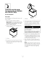
Page 17: ...e electrolyte to soak into the plates Refill as necessary to bring the electrolyte to within about 1 4 inch 6 mm of the bottom of the fill well Figure 4 Charging the battery produces gasses that can explode Never smoke near the battery and keep sparks and flames away from battery 5 Connect a 3 to 4 amp battery charger to the battery posts Charge the battery at a rate of 3 to 4 amps until the specific ...

Page 18: ...e when pushed 8 First install the positive cable red to the positive terminal and then the negative cable black to the negative terminal of the battery Slide the rubber boot over the positive terminal to prevent a possible short from occurring Incorrect battery cable routing could damage the machine and cables causing sparks Sparks can cause the battery gasses to explode resulting in personal inju...

Page 19: ... bar push the bar forward to relieve pressure on the pins remove the pins lower the bar slowly and secure it with the pins so that it does not damage the hood Step 4 Checking the Tire Pressure No Parts Required Procedure The tires are over inflated for shipping Therefore release some of the air to reduce the pressure The correct air pressure is 15 psi 103 kPa in the rear tires and 25 psi 172 kPa in...

Page 20: ...Mower Weight Required with a 72 inch 183 cm Side discharge Mower Groundsmaster 7210 Traction Unit with no Added Attachments 22 lb 10 kg 0 lb 0 kg 0 lb 0 kg Groundsmaster 7210 Traction Unit and Hard Canopy 75 lb 34 kg 21 lb 9 5 kg 33 lb 15 kg Groundsmaster 7210 Traction Unit Hard Canopy and Road Light Kit 71 lb 32 2 kg 63 lb 28 5 kg 22 lb 10 kg Groundsmaster 7210 Traction Unit Hard Canopy Road Ligh...

Page 21: ...Engine Oil Level in Engine Maintenance page 46 3 Check the cooling system before starting the engine refer to Checking the Cooling System in Cooling System Maintenance page 53 Step 7 Reading the Manuals and Viewing the DVD Parts needed for this step 1 Operator s Manual 1 Engine Operator s Manual 1 Parts Catalog 1 Operator Training DVD 1 Pre delivery Inspection Sheet 1 Engine warranty 1 CE certi ca...

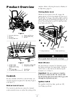
Page 22: ...ward in Operation page 25 Parking Brake Lever Whenever the engine is shut off engage the parking brake to prevent accidental movement of the machine To engage the parking brake pull the parking brake lever rearward and up Figure 8 To release the parking brake push the parking brake lever forward and down Figure 8 1 Parking brake lever 2 Mower deck lift lever Do not park the traction unit on a slop...

Page 23: ...Engine Coolant Temperature Warning Light This light glows and the cutting blades stop if the engine coolant temperature is high If the machine is not stopped and the coolant temperature rises another 20 F the engine will stop Important If the mower deck shuts down and the temperature warning light is on push PTO knob down drive to a safe flat area move the throttle lever to the Slow position move t...

Page 24: ... 30360TE 30360TC 30363 30363TE and 30363TC 2220 lb 1007 kg Weight Model 30361 and 30364 2196 lb 996 kg Weight Model 30362 and 30365 2142 lb 971 4 kg Attachments Accessories A selection of Toro approved attachments and accessories are available for use with the machine to enhance and expand its capabilities Contact your Authorized Service Dealer or Distributor or go to www Toro com for a list of al...

Page 25: ...ch may plug filters Use of summer grade diesel fuel above 20 F 7 C will contribute toward longer life of the pump components Important Do not use kerosene or gasoline instead of diesel fuel Failure to observe this caution will damage the engine Fuel is harmful or fatal if swallowed Long term exposure to vapors can cause serious injury and illness Avoid prolonged breathing of vapors Keep face away f...

Page 26: ...k to the other It is important when filling that you park on a level surface If you park on a hill you may inadvertently overfill the tanks 2 Shut the engine off and set the parking brake 3 Clean around each fuel tank cap and remove the cap Important Do not open the fuel tanks when parked on a hill The fuel could spill out 4 Add fuel to both fuel tanks until the level is even with the bottom of the ...

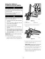
Page 27: ...ical wires before driving under any objects and do not contact them Important Lower the roll bar only when absolutely necessary 1 To lower the roll bar remove the hairpin cotters push the roll bar forward against the springs and remove the two pins Figure 11 Figure 11 1 Roll bar 3 Pin 2 Raised position 4 Hairpin cotter 2 Lower the roll bar to the down position Figure 12 Figure 12 3 Install the two...

Page 28: ...id loss of control and possibility of rollover Do not operate near drop offs or near water Reduce speed and use extreme caution on slopes Avoid sudden turns or rapid speed changes Figure 13 1 Safe Zone 3 Water 2 Use walk behind mower and or hand trimmer near drop offs and water This machine produces sound levels in excess of 85 dBA at the operators ear and can cause hearing loss through extended p...

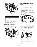
Page 29: ...nsure that the motion controls are in the neutral locked position 3 Set the parking brake refer to Setting the Parking Brake 4 Move the PTO power take off switch to the off position Figure 16 Figure 16 1 Ignition switch 3 Glow plug light 2 Throttle control 4 Power take off switch PTO 5 Move the throttle lever midway between the Fast and Slow positions Figure 16 6 Turn the ignition key clockwise to...

Page 30: ...ne Important Make sure to remove the key as the fuel pump or accessories may run and cause the battery to lose charge Children or bystanders may be injured if they move or attempt to operate the tractor while it is unattended Always remove the ignition key and set the parking brake when leaving the machine unattended even if just for a few minutes Driving the Machine The throttle control regulates...

Page 31: ...es and lowers the mower deck Figure 19 The engine must be running for you to use this lever Figure 19 1 Deck lift lever To lower the mower deck push the lever forward To raise the mover deck pull the lever rearward Important Do not continue to hold the lever back or forward after the mower has fully raised or lowered Doing so will damage the hydraulic system Note To lock the mower deck in a raised...

Page 32: ...lus 1 4 inch 6 mm The third row down gives you the height listed plus 1 2 inch 12 mm The bottom row gives you the height listed plus 3 4 inch 18 mm For the 6 inch 15 8 cm position there is only one hole located in the second row This does not add 1 4 inch 6 mm to the 6 inch 15 8 cm position Figure 21 1 Deck lift lever 3 Height of cut stop 2 Stop pin 4 Adjust the anti scalp rollers and skids as req...

Page 33: ...e motion control levers to the neutral locked position and set the parking brake 2 Move the throttle lever to the Slow position stop the engine remove the key and wait for all moving parts to stop before leaving the operating position 3 After adjusting the height of cut adjust the rollers by removing the flange nut bushing spacer and bolt Figure 23 Figure 23 1 Flange nut 4 Spacer 2 Bushing 5 Bolt 3...

Page 34: ...jack stands 4 Remove the fasteners securing each roller on your mower deck and move the rollers up or down as desired refer to Figure 25 through Figure 29 as applicable for your mower Figure 25 All Mower Decks 1 Front roller 2 Roller shaft Figure 26 Guardian Mower Decks Only 1 Bolt 4 Nut 2 Rear under deck roller 5 Bracket 3 Spacer Figure 27 Guardian Mower Decks Only 1 Bolt 3 Nut 2 Front under deck...

Page 35: ...r the safety system immediately 1 Sitting on the seat engage the parking brake and move the PTO to on Try starting the engine the engine should not crank 2 Sitting on the seat engage the parking brake and move the PTO to off Move either motion control lever out of neutral locked position Try starting the engine the engine should not crank Repeat for other control lever 3 Sitting on the seat engage...

Page 36: ... system 3 Operator is in the seat 4 The PTO is On 5 The parking brake is not engaged 6 Controls are in Neutral 7 The SCM is receiving power and is operational Positioning the Seat Changing the Seat Position The seat can move forward and backward Position the seat where you have the best control of the machine and are most comfortable 1 To adjust move the lever sideways to unlock the seat Figure 32...

Page 37: ... slide the seat all the way forward 2 Push one of the seat latches located behind and to the sides of the seat rearward to unlatch the seat and pull forward on the top of the seat Figure 34 Figure 34 1 Seat latch Pushing the Machine by Hand If the machine breaks runs out of fuel etc you may need to push it To do so you first need to open the hydraulic by pass valves Important Always push the machin...

Page 38: ...use mower components to get caught as the unit moves from ramp to trailer or truck Steeper angles may also cause the unit to tip backward If loading on or near a slope position the trailer or truck so it is on the down side of the slope and the ramp extends up the slope This will minimize the ramp angle The trailer or truck should be as level as possible Important Do not attempt to turn the unit w...

Page 39: ... are adequate for the load you are pulling and that they meet all local traffic regulations for your area Lock the brake and block the wheels Securely fasten the machine to the trailer or truck with straps chains cable or ropes as required by local traffic regulations in your area Figure 37 Figure 37 1 Front tie down left side shown 2 Rear tie downs Operating Tips Fast Throttle Setting Ground Speed ...

Page 40: ...mower after each use If grass and dirt build up inside the mower cutting quality will eventually become unsatisfactory Blade Maintenance Maintain a sharp blade throughout the cutting season because a sharp blade cuts cleanly without tearing or shredding the grass blades Tearing and shredding turns grass brown at the edges which slows growth and increases the chance of disease Check the blades dail...

Page 41: ...Check battery cable connections Check the tire pressure Check the condition of the blade drive belts on the mower deck Every 150 hours Check the lubricant in the mower deck gear box Change the engine oil and lter Every 200 hours Inspect cooling system hoses and seals Replace them if cracked or torn Check the alternator belt tension Torque wheel lug nuts Every 400 hours Change the mower deck gear b...

Page 42: ...or Check Air Filter Restriction Indicator3 Check Radiator Screen for Debris Check Unusual Engine Noises1 Check Unusual Operating Noises Check Hydraulic Hoses for Damage Check Fluid Leaks Check Tire Pressure Check Instrument Operation Check Condition of Blades Lubricate All Grease Fittings2 Touch up Damaged Paint 1 Check glow plug and injector nozzles if hard starting excess smoke or rough running ...

Page 43: ...50 hours of operation Bearings and bushings must be lubricated daily when operating conditions are extremely dusty and dirty Dusty and dirty operating conditions could cause dirt to get into the bearings and bushings resulting in accelerated wear Lubricate the grease fittings immediately after every washing regardless of interval specified 1 Wipe the grease fittings clean so foreign matter cannot be ...

Page 44: ...Figure 39 44 ...

Page 45: ...The gear box is designed to operate with SAE 80 90 gear lube Although the gear box is shipped with lubricant from the factory check the level before operating the cutting unit for the first time and every 150 operating hours thereafter Change the lubricant in the gear box every 400 operating hours Checking the Mower Deck Gear Box Lubricant 1 Position the machine and cutting unit on a level surface ...

Page 46: ...l locked position and set the parking brake 4 Move the throttle lever to the Slow position stop the engine remove the key and wait for all moving parts to stop before leaving the operating position 5 Lift the footrest exposing the top of the mower deck 6 Remove the dipstick fill plug from the top of the gear box Figure 41 7 Place a funnel and drain pan under the drain plug located under the front o...

Page 47: ...at it in the canister Important Do not apply pressure to the flexible center of the filter 8 Clean the dirt ejection port located in the removable cover as follows A Remove the rubber outlet valve from the cover Figure 42 B Clean the cavity C Replace the outlet valve 9 Install the cover orienting the rubber outlet valve in a downward position between approximately 5 00 to 7 00 when viewed from the e...

Page 48: ...hen every 150 hours of operation thereafter If possible run the engine just before changing the oil because warm oil flows better and carries more contaminants than cold oil 1 Position the machine on a level surface 2 Open the hood 3 Set a drain pan under the oil pan and in line with the drain plug Figure 44 Figure 44 1 Oil lter 2 Drain plug 4 Clean the area around the drain plug 5 Remove the drain...

Page 49: ...operation 1 Place a clean container under the fuel filter 2 Loosen the drain plug on the bottom of the filter canister Figure 45 1 Water separator 2 Drain plug 3 Clean the area where the filter canister mounts 4 Remove the filter canister and clean the mounting surface 5 Lubricate the gasket on the filter canister with clean oil 6 Install the filter canister by hand until the gasket contacts mounting su...

Page 50: ...ace a rag under the air bleed screw on the fuel injection pump and open it Figure 47 Figure 47 1 Fuel injection pump bleed screw 4 Turn the key in the ignition switch to the On position The electric fuel pump will begin operation thereby forcing air out around the air bleed screw The engine may start during this procedure Moving fans and belts in a running engine can severely injure you or bystand...

Page 51: ...ortant Whenever working with the electrical system always disconnect the battery cables negative cable first to prevent possible wiring damage from short outs Servicing the Battery Warning CALIFORNIA Proposition 65 Warning Battery posts terminals and related accessories contain lead and lead compounds chemicals known to the State of California to cause cancer and reproductive harm Wash hands after ...

Page 52: ...tery in a cool atmosphere to avoid quick deterioration of the charge in the battery To prevent the battery from freezing make sure it is fully charged The specific gravity of a fully charged battery is 1 265 1 299 Checking the Fuses The fuses are located under the control panel Access them through the side panel cover Figure 49 To open the side panel cover release the 2 latches and pull out on it I...

Page 53: ...ing the cone bearings and seals packed with grease into the wheel hub positioned as shown in Figure 52 6 Slide the spacer into the wheel hub through the bearings captivating the spacer inside the wheel hub with 2 bearing spacers Important Ensure that the seal lips are not folded in 7 Install the castor wheel assembly between the castor fork and secure it in place with the bolt and locknut 8 Tighte...

Page 54: ... the expansion tank Figure 53 The coolant level should be between the marks on the side of the tank Figure 53 1 Expansion tank 2 If coolant level is low remove the expansion tank cap and replenish the system Do not overfill 3 Install the expansion tank cap Cleaning the Radiator To prevent the engine from overheating the radiator must be kept clean Normally check the radiator daily and if necessary ...

Page 55: ...0 015 to 0 045 inch 0 4 to 1 mm 4 Move the switch toward the tab on the brake shaft until the distance between the tab and switch body is 0 015 to 0 045 inch 0 4 to 1 mm Figure 55 5 Secure the switch 6 Test the adjustment as follows A Ensure that the parking brake is engaged and you are not sitting on the seat then start the engine B Move the control levers out of the neutral locked position The e...

Page 56: ... aside 3 Using a breaker bar or similar tool move the idler pulley for the top belt Figure 57 away from the top drive belt to release the belt tension and allow the belt to be slipped off the pulleys Figure 57 1 Top belt 3 Bottom belt 2 Top idler pulley 4 Bottom idler pulley 4 Using a breaker bar or similar tool move the idler pulley for the bottom belt Figure 57 away from the bottom drive belt to...

Page 57: ...ith the neutral slots when released from the reverse drive position adjustment is required Adjust each lever spring and rod separately 1 Disengage the PTO move the motion control levers to the neutral locked position and set the parking brake 2 Move the throttle lever to the Slow position stop the engine remove the key and wait for all moving parts to stop before leaving the operating position 3 R...

Page 58: ...e made with drive wheels turning Mechanical or hydraulic jacks may fail to support machine and cause a serious injury Use jack stands when supporting machine Do not use hydraulic jacks The engine must be running to perform this adjustment Contact with moving parts or hot surfaces may cause personal injury Keep hands feet face clothing and other body parts away from rotating parts muffler and other ...

Page 59: ...t switch Electrical system will not perform proper safety shut off with jumper wire installed Remove jumper wire from wire harness connector and plug connector into seat switch when adjustment is completed Never operate this unit with jumper installed and seat switch bypassed 12 Lower the seat into position 13 Remove the jack stands Adjusting the Maximum Ground Speed 1 Disengage the PTO move the m...

Page 60: ...you will likely have to test your adjustment several times Ensure that the machine drives straight and does not turn when both control levers are pushed all the way forward If the machine turns you do not have the stop bolts evenly set and will need to adjust them further Adjusting the Tracking 1 Disengage the PTO move the motion control levers to the neutral locked position and set the parking br...

Page 61: ... One bottle is sufficient for 4 6 gal 15 22 1 of hydraulic oil Order part number 44 2500 from your authorized Toro distributor Checking the Hydraulic System Check the level of the hydraulic fluid before the engine is first started and daily thereafter 1 Position the machine on a level surface Place the controls in the neutral locked position and start the engine Run engine at lowest possible RPM to p...

Page 62: ...ediately install a new hydraulic oil filter 6 Install the hydraulic reservoir and transmission case drain plugs 7 Fill the reservoir to the proper level approximately 6 quarts refer to Checking the Hydraulic Fluid 8 Start the engine and check for oil leaks Allow the engine to run for about five minutes then shut it off 9 After two minutes check the level of the hydraulic fluid refer to Checking the H...

Page 63: ...ea resulting in serious personal injury or death Inspect the blade periodically for wear or damage Replace a worn or damaged blade Inspect and check the blades every 8 hours Before Inspecting or Servicing the Blades 1 Disengage the PTO move the motion control levers to the neutral locked position and set the parking brake 2 Move the throttle lever to the Slow position stop the engine remove the ke...

Page 64: ...g brake 2 Move the throttle lever to the Slow position stop the engine remove the key and wait for all moving parts to stop before leaving the operating position 3 Rotate the blades until the ends face forward and backward Figure 72 Measure from a level surface to the cutting edge position A of the blades Figure 72 Note this dimension Figure 72 1 Measure here from blade to hard surface 2 Position ...

Page 65: ...pindle shaft Figure 75 Sharpening the Blades When sharpening blade pieces of blade could be thrown and cause serious injury Wear proper eye protection when sharpening blades 1 Sharpen the cutting edge at both ends of the blade Figure 73 Maintain the original angle The blade retains its balance if the same amount of material is removed from both cutting edges Figure 73 1 Sharpen at original angle 2...

Page 66: ...to the front tip of the cutting edge 8 Adjust the jam nuts securing the deck yokes chains to the mower deck until the mower deck is level Figure 76 1 Chain 3 Jam nut 2 Yoke 4 Mower deck Adjusting the Mower Deck Pitch Cutting unit pitch is the difference in height of cut from the front of the blade plane to the back of the blade plane Toro recommends a blade pitch of approximately 5 16 inch 8 mm Th...

Page 67: ...orn grass deflector Figure 78 1 Bolt 5 Spring installed 2 Spacer 6 Grass De ector 3 Locknut 7 Left hand hook end of spring place behind deck edge before installing bolt 4 Spring 8 Right hand hook end of spring 3 Place the spacer and spring between the replacement grass deflector brackets Figure 78 Place the left hand J hook end of the spring behind the deck edge Note Make sure the left hand J hook e...

Page 68: ... of the machine by using jack stands 5 Thoroughly clean the underside of the mower with water Waste Disposal Engine oil batteries hydraulic oil and engine coolant are pollutants to the environment Dispose of these according to your state and local regulations 68 ...

Page 69: ...up paint on painted areas that are scratched chipped or rusted Repair any dents in the metal body 7 Service the battery and cables as follows A Remove the battery terminals from the battery posts B Clean the battery terminals and posts with a wire brush and baking soda solution C Coat the cable terminals and battery posts with Grafo 112X skin over grease Toro Part No 505 47 or petroleum jelly to p...

Page 70: ...Schematics Electrical Schematic Rev A 70 ...

Page 71: ...Hydraulic Schematic Rev A 71 ...

Page 72: ...e not limited to weather storage practices contamination use of unapproved coolants lubricants additives or chemicals etc Normal wear and tear items Normal wear and tear includes but is not limited to damage to seats due to wear or abrasion worn painted surfaces scratched decals or windows etc Parts Parts scheduled for replacement as required maintenance are warranted for the period of time up to ...

Reviews: