background image

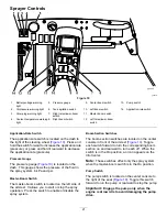
Brake Pedal

Use the brake pedal to stop or slow the sprayer
(

Figure 8

).

CAUTION

If you operate the sprayer with poorly adjusted
or worn brakes, you could lose control of the
sprayer, resulting in serious injury or death
to you or bystanders.

Always check the brakes before operating the
sprayer and keep them properly adjusted and
repaired.

Parking Brake

The parking brake is a pedal to the left of the brake
(

Figure 8

). Engage the parking brake whenever you

plan on leaving the seat to prevent the sprayer from
accidently moving. To engage the parking brake,
press the brake pedal and, while holding the brake,
press the parking-brake pedal. To disengage, press
and release the brake pedal. If the sprayer is parked
on a steep grade, apply the parking brake and place
blocks on the downhill side of the wheels.

Ignition Switch

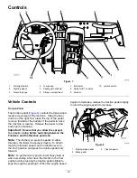
The ignition switch (

Figure 8

), used to start and shut

off the engine, has 3 positions: O

FF

, O

N

/P

REHEAT

,

and S

TART

.

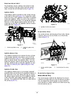
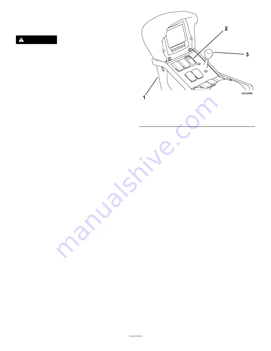
Speed-Lock Switch

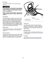
The speed-lock switch locks the position of the traction
pedal at the time that the switch is set (

Figure 9

). This

ensures that the sprayer travels at a constant speed
while you are driving the machine on level ground.

g032469

Figure 9

1.

Center console

3.

Throttle lever

2.

Speed-lock switch

Throttle Lever

The throttle lever, located on the control panel
between the seats (

Figure 9

), controls the speed of

the engine. Push the lever forward to increase the
engine speed and pull it rearward to decrease the
engine speed.

Work-Light Switch

Toggle the switch to operate the work lights (

Figure

7

). Push it forward to turn the lights on and rearward

to turn them off.

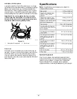
Fuel Gauge

The fuel gauge on the dash of the machine and
displays the level of the fuel in the tank (

Figure 7

).

20


Summary of Contents for Multi Pro 5800-D

Page 1: ...Form No 3404 825 Rev D Multi Pro 5800 D Turf Sprayer Model No 41593 Serial No 316000001 and Up Register at www Toro com Original Instructions EN 3404 825 D ...

Page 2: ...ncy EPA and the California Emission Control Regulation of emission systems maintenance and warranty Replacements may be ordered through the engine manufacturer Introduction Read this manual carefully to learn how to operate and maintain your product properly The information in this manual can help you and others avoid injury and product damage Although Toro designs and produces safe products you a...

Page 3: ...oncern 49 Pre Maintenance Procedures 50 Raising the Sprayer 50 Accessing the Engine 50 Lubrication 52 Greasing the Sprayer 52 Greasing the Boom Hinges 52 Greasing the Actuator Rod Bearings 53 Engine Maintenance 54 Checking the Air Cleaner 54 Servicing the Engine Oil 56 Fuel System Maintenance 58 Checking the Fuel Line and Connections 58 Bleeding the Fuel System 58 Bleeding Air from the Injectors 5...

Page 4: ...raining Read the Operator s Manual and other training material before operating the machine Note If the operator s or mechanic s cannot read the manual language it is the owner s responsibility to explain this material to them Become familiar with the safe operation of the equipment operator controls and safety signs All operators and mechanics should be trained The owner is responsible for traini...

Page 5: ...E to guard against personal contact with chemicals such as the following safety glasses goggles and or face shield respirator or filter mask chemical resistant gloves rubber boots or other substantial footwear hearing protection keep on hand a clean change of clothes soap and disposable towels in the event of a chemical spill Keep in mind that there may be more than 1 chemical used and information...

Page 6: ...uvers or other unsafe driving actions that may cause a loss of sprayer control Before backing up look to the rear and ensure that no one is behind you Back up slowly Watch out for traffic when you are near or crossing roads Always yield the right of way to pedestrians and other vehicles This sprayer is not designed for use on streets or highways Always signal your turns or stop early enough so tha...

Page 7: ...denly apply the brakes when rolling backward as this may cause the sprayer to overturn Reduce speed and load when operating on rough terrain uneven ground and near curbs holes and other sudden changes in terrain Loads may shift causing the sprayer to become unstable WARNING Sudden changes in terrain may cause abrupt steering wheel movement possibly resulting in hand and arm injuries Use care when ...

Page 8: ...ering this sprayer in any manner that may affect sprayer operation performance durability or its use may result in injury or death Such use could void the product warranty Sound Power This unit has a guaranteed sound power level of 99 dBA which includes an Uncertainty Value K of 1 dBA Sound power level was determined according to the procedures outlined in ISO 11094 Sound Pressure This unit has a ...

Page 9: ... not touch the hot surface 2 Explosion hazard read the Operator s Manual 4 Warning read the Operator s Manual decal107 8667 107 8667 1 Jacking 2 Jack point locations 3 Warning Read the Operator s Manual for more information on jacking the vehicle decal107 8722 107 8722 1 Engaging the parking brake 1 Push down on the parking brake pedal 2 Pull down on the parking brake lever to lock the parking bra...

Page 10: ...N m 75 to 90 ft lb decal117 2718 117 2718 decal117 4955 117 4955 1 Warning read the Operator s Manual wear the seat belt when seated in the operator s position avoid tipping the machine 2 Warning wear hearing protection decal119 6035 119 6035 1 Engine shut off 3 Engine start 2 Engine run preheat decal120 0616 120 0616 1 Warning read the Operator s Manual use fresh clean water for first aid washing...

Page 11: ... location 2 Tie down locations 3 Warning Read the Operator s Manual decal120 0624 120 0624 1 Crushing dismemberment hazard of bystanders do not exit or enter the machine while it is moving stop the machine before entering or exiting 2 Falling crushing hazard no riders on tank keep arms and legs inside of the vehicle at all times use passenger handholds decal120 0625 120 0625 1 Pinch point hand kee...

Page 12: ... 6982 127 6982 1 Pump return flow 2 Boom spray decal132 7689 132 7689 1 Auto 7 Rinse system off 2 Spray mode 8 Sonic sensor on 3 Manual spray mode 9 Sonic sensor off 4 Foam marker on 10 Application rate increase 5 Foam marker off 11 Application rate decrease 6 Rinse system on decal132 7708 132 7708 1 Headlight on 3 Horn 2 Headlight off 12 ...

Page 13: ...ly when traveling across or up and down slopes 2 Warning do not operate this machine unless you are trained 6 To start the engine engage the parking brake insert the ignition key and turn it to the START position 3 Warning stay away from moving parts keep all guards and shields in place 7 To shut off the engine press the brake ensure the traction pedal is in the Neutral position set the parking br...

Page 14: ...ft boom spray 2 Pump off 6 Speed control off 10 Raise the right boom 14 Center boom spray 3 Agitation on 7 Lower the left boom 11 Engine speed fast 15 Right boom spray 4 Agitation off 8 Raise the left boom 12 Engine speed slow decal132 7786 132 7786 1 Spray off 3 USB 2 Spray on 14 ...

Page 15: ...of the machine from the normal operating position Note If you have questions or need additional information regarding the spray control system refer to the Operator s Manual supplied with the system Important This sprayer is sold without nozzles To use the sprayer you must obtain and install nozzles Contact your Authorized Toro Distributor for information on the available boom kit and accessories ...

Page 16: ... 1 If necessary remove the packing components that secure the right and left extension booms during shipping 2 Support the booms while they are extended to the spray position 3 At the boom hinge measure the compressed height of the upper and lower springs Figure 3 Note You must measure and adjust compressed spring height while the booms in the extended horizontal position A Compress all springs un...

Page 17: ...e the bolts washers and nuts that secure the shipping bumper to the front chassis plate Figure 4 g028179 Figure 4 1 Nut 3 Washer 2 Shipping bumper 4 Bolt 2 Remove the shipping bumper from the machine Figure 4 Note Discard the bolts washers nuts and shipping bumper 17 ...

Page 18: ...Pump 2 Operator s seat 5 Tank lid 8 Battery 3 Fresh water tank 6 Chemical tank 9 Work lights g032457 Figure 6 1 Boom control cylinder 4 Fuel tank 7 Center boom section 2 Boom transport cradle 5 Hydraulic tank 8 Tank drain valve 3 Valve manifolds 6 Right boom section 9 Left boom section 18 ...

Page 19: ...ine Important Ensure that you allow the sprayer to come to a stop before switching between the FORWARD and the REVERSE positions Note The farther you press the pedal in either direction the faster the sprayer travels To obtain maximum forward speed set the throttle lever to the FAST position and press the traction pedal fully forward Note To get maximum power under heavy load or when ascending a h...

Page 20: ...ce blocks on the downhill side of the wheels Ignition Switch The ignition switch Figure 8 used to start and shut off the engine has 3 positions OFF ON PREHEAT and START Speed Lock Switch The speed lock switch locks the position of the traction pedal at the time that the switch is set Figure 9 This ensures that the sprayer travels at a constant speed while you are driving the machine on level groun...

Page 21: ...h This gauge shows the pressure of the fluid in the spray system in kPa and psi Master Boom Switch The master boom switch is located on the left side of the armrest It allows you to start or stop the spray operation Press the switch to enable or disable the spray system Boom Section Switches The boom section switches are located on the center console in front of the armrest Figure 10 Toggle each s...

Page 22: ...n valve You can adjust the bypass valve to ensure that the pressure remains constant when cycling the agitation on and off refer to Calibrating the Agitation Bypass Valve page 44 Agitation Throttle Valve The agitation throttle valve is a manually operated ball valve that controls flow to the agitation nozzles in the main tank This valve allows the user to control the sprayer system pressure at the...

Page 23: ...Note Specifications and design are subject to change without notice Base weight 1307 kg 2 882 lb Weight with standard spray system empty without operator 1307 kg 2 882 lb Weight with standard spray system full without operator 2499 kg 5 510 lb Maximum gross vehicle weight GVW on level ground 3023 kg 6 665 lb Tank capacity 1136 L 300 US gallons Overall width with standard spray system booms stored ...

Page 24: ...e 66 Checking the Hydraulic System Before you start the engine and use the machine check the hydraulic system refer to Checking the Hydraulic Fluid page 69 Checking the Tire Pressure Service Interval Before each use or daily Check the tire air pressure to ensure proper levels Fill the tires to 138 kPa 20 psi Note Also check the tires for wear or damage Checking the Brakes Service Interval Before e...

Page 25: ...t meet specification ASTM D6751 or EN14214 The blended fuel composition should meet ASTM D975 or EN590 Painted surfaces may be damaged by biodiesel blends Use B5 biodiesel content of 5 or lesser blends in cold weather Monitor seals hoses gaskets in contact with fuel as they may degrade over time Fuel filter plugging may be expected for a time after converting to biodiesel blends Contact your distr...

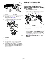
Page 26: ...with the retainer that you removed in step 2 Inspecting the Tank Straps Service Interval Before each use or daily Check the tank straps Important Over tightening the tank strap fasteners can result in deforming and damaging the tank and straps 1 Fill the main tank with water 2 Check to see if there is any movement between the tank straps and the tank Figure 18 g028263 Figure 18 1 Rear tank strap 4...

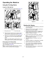
Page 27: ...e up position when the parking brake disengages g038517 Figure 20 Starting the Engine 1 Sit on the operator s seat and keep your foot off the traction pedal 2 Make sure that the pump agitation and boom switches are in the OFF position 3 Ensure that the parking brake is engaged the traction pedal is in the NEUTRAL position the throttle is in the SLOW position 4 Turn the switch to the ON PREHEAT pos...

Page 28: ...ht on the switch turns off and the traction control returns to the traction pedal Shutting Off the Engine 1 Move all controls to the NEUTRAL position 2 Press the brake to stop the sprayer 3 Set the parking brake 4 Move the throttle lever to the IDLE SLOW position 5 Turn the starter key to the OFF position 6 Remove the key from the starter switch to prevent someone from accidentally starting the en...

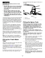
Page 29: ...r mixing any chemicals The fresh water tank is located on the ROPS behind the passenger seat Figure 21 It supplies a source of fresh water for you to wash chemicals off your skin eyes or other surfaces in the case of accidental exposure To fill the tank unscrew the cap on the top of the tank fill the tank with fresh water and replace the cap To open the fresh water tank spigot turn the lever on th...

Page 30: ...ct the booms stop the sprayer on level ground 4 Use the boom lift switches to raise the booms Note Raise the booms until they are completely in the boom transport cradle forming the X transport position and the boom cylinders are fully retracted Important To prevent damage to the boom actuator cylinder make sure that the actuators are fully retracted before transport Important Release the actuator...

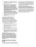
Page 31: ...ated sub menu screens g035344 Figure 22 Splash Screen Home Screen When you start the machine the home screen appears displaying the corresponding icons that apply i e the parking brake is engaged the boom sections are in the ON position the operator is out of the seat etc Note The following figure is an example screen this screen is meant to show all the potential icons that could appear on the sc...

Page 32: ... center boom sections display when any of the boom sections are in the ON position Figure 23 Vehicle Speed Indicator The vehicle speed indicator displays the current vehicle speed Figure 23 Parking Brake Indicator The parking brake indicator displays when the parking brake is engaged Figure 23 Operator s Seat Indicator The operator seat indicator displays when the operator is out of the seat Figur...

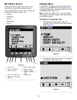
Page 33: ...t save icon 5 Button 3 context sensitive selector Settings Menu To access the Settings screen press either button 1 or button 2 on the Main Menu screen Figure 24 to navigate Settings option and press button 4 to select the Settings option Figure 24 Note This screen allows you to view and change the settings for the tank display boom width and to reset default settings Setting the Tank Agitation Fl...

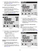
Page 34: ...on 5 to save your setting exit the Units screen and return to the Main screen Adjusting the Display Backlighting and Contrast 1 At the Settings screen press button 2 to navigate to the Display option and then press button 4 to select the Display 2 At the Display menu screen press button 2 to navigate to the Backlight option or the Contrast option Figure 28 g034287 Figure 28 3 Press button 3 raise ...

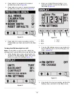
Page 35: ... that are secured with the PIN 1 At the Display menu screen press button 2 to navigate to the PIN Settings option then press button 4 to select PIN Settings Figure 31 g034290 Figure 31 2 Enter your 4 digit PIN using buttons 1 to 4 and press button 5 to enter the PIN into the InfoCenter Figure 32 g034292 Figure 32 1 Digit 1 4 Digit 4 2 Digit 2 5 Enter 3 Digit 3 3 From the PIN Settings screen press ...

Page 36: ...en press button 4 to select PIN Change Figure 34 g034303 Figure 34 4 I the Enter Old PIN screen enter your old PIN using buttons 1 to 4 and press button 5 to enter the PIN into the InfoCenter Figure 32 Note The default PIN when you initially create your PIN is 1234 g034306 Figure 35 1 Digit 1 4 Digit 4 2 Digit 2 5 Enter PIN 3 Digit 3 5 In the Enter New PIN screen enter your new PIN using buttons 1...

Page 37: ...do so the machine automatically uses the current calibration rates g035662 Figure 39 Preparing for the Speed Calibration 1 Ensure that the tires are properly inflated refer to Checking the Tire Pressure page 24 2 To access the Speed screen press button 2 on the Calibrate screen until you reach Speed then press button 4 Figure 39 to select Speed 3 Set the parking brake and fill the sprayer tank wit...

Page 38: ...e distance traveled 5 If the calibration is successful a Calibration Successful screen appears press button 5 to exit 6 If the calibration is not successful a Calibration Failed screen appears with the reasoning behind why the calibration failed press button 5 to exit and restart the calibration 7 Set the parking brake shut off the engine and remove the key from the key switch Manual Calibration E...

Page 39: ...ur pumps booms and engine input and output Figure 43 Select Fault Viewer on the Diagnostics screen to view all faults that have occurred on the machine Figure 43 g034283 Figure 43 About Screen To access the About screen press button 2 on the Main Menu screen Figure 24 until you reach About and press button 4 to select About Figure 44 This screen displays the model number and serial number of your ...

Page 40: ...itch active To start turn pump off Start Prevented 3 Not in NEUTRAL To start return traction pedal to neutral Start Prevented 4 Out of seat To start must be seated or set the parking brake Start Prevented 5 Starter engage timeout To start rest starter Start Prevented 6 Rinse pump active To start turn off rinse pump Engine Stopped 102 Out of seat Engine stop due to operator out of seat Engine Stopp...

Page 41: ...tion and the boom cylinders are fully retracted whenever you move the sprayer from a spraying area to another or move to a storage or cleaning area Taking Proper Turf Care Precautions while Operating in Stationary Modes Important Under some conditions heat from the engine radiator and muffler can potentially damage grass when operating the sprayer in a stationary mode Stationary modes include tank...

Page 42: ...e approved clean rinse kit for this machine Contact your Authorized Toro Dealer for more information Clean the spray system after each spraying session To properly clean the spray system Use 3 separate rinses Use the cleaners and neutralizers as recommended by the chemical manufacturers Use pure clean water no cleaners or neutralizers for the last rinse 1 Stop the sprayer set the parking brake and...

Page 43: ...n the strainer after each tank 2 Apply chemical neutralizer the boom section do the sprayer and the back area of the frame of the machine 3 Use a garden hose to rinse off the outside of the sprayer and machine with clean water 4 Remove the nozzles and clean them by hand Note Replace damaged or worn nozzles Setting the Boom Section Bypass Valves Manual Mode Only Important When operating in Auto mod...

Page 44: ...e Spray System installed turn the power switch to the OFF position 1 Select an open flat area to perform this procedure 2 Fill the spray tank halfway with clean water 3 Verify the agitation control valve is open Note If it has been adjusted open it completely at this time 4 Set the parking brake and start the engine 5 Set the pump switch and the agitation switch to the ON position 6 Move the throt...

Page 45: ...sulting in personal injury Never tow the sprayer faster than 4 8 km h 3 mph Towing the sprayer is a 2 person job If the machine must be moved a considerable distance transport it on a truck or trailer refer to Transporting the Sprayer page 46 1 Rotate the tow valve Figure 52 90 in either direction to open it g002212 Figure 52 1 Tow valve Important If you do not open the tow valve before towing the...

Page 46: ...and torque it to no more than 7 to 11 N m 5 to 8 ft lb Transporting the Sprayer For moving the sprayer long distances use a trailer Secure the sprayer to the trailer Also ensure that the booms are tied down and secure Figure 55 and Figure 56 illustrate the tie down points g002210 Figure 55 1 Tie down points g002211 Figure 56 1 Rear tie down point 46 ...

Page 47: ...e suction strainer more often when using wettable powders Check the tank straps Check the air cleaner more frequently if operating conditions are extremely dusty or sandy Check the engine oil Check the coolant level Check the hydraulic fluid level Every 50 hours Lubricate the pump Lubricate all grease fittings Check the battery cable connections Every 100 hours Lubricate the boom hinges Torque the...

Page 48: ...d change if necessary Replace the hydraulic fluid filters Change the hydraulic fluid Inspect the O rings in the valve assemblies and replace them if necessary Change the pressure filter Inspect the pump diaphragm and replace if necessary see an Authorized Toro Service Distributor Inspect the pump check valves and replace if necessary see an Authorized Toro Service Distributor Inspect the nylon piv...

Page 49: ...filter Inspect the radiator and oil cooler for debris Check any unusual engine noises Check any unusual operating noises Check the tire pressure Check for fluid leaks Check all hydraulic and fluid hoses for damage kinks or wear Check the instrument operation Check the accelerator operation Clean the suction strainer Lubricate all grease fittings1 Touch up any damaged paint 1Immediately after every...

Page 50: ...h jack stands The jacking point at the front of the sprayer is under the front axle directly under the leaf springs Figure 57 g002215 Figure 57 1 Front jacking points The jacking point at the rear of the sprayer is on the rear side where the boom supports are Figure 58 g002216 Figure 58 1 Rear jacking points Accessing the Engine Removing the Forward Heat Shield 1 Set the parking brake stop the pum...

Page 51: ...50 4 Torque the bolts to 1 129 to 1 582 N cm 100 to 140 in lb 5 Remove the jack stands and lower the machine Removing the Seat Base Access Panel 1 Remove the 2 flanged head bolts that secure the seat base access panel to the seat base Figure 61 g032998 Figure 61 1 Seat base access panel 3 Hole seat base 2 Flanged head bolt 2 Remove the seat base access panel from the machine Figure 61 Installing t...

Page 52: ...ss grease The grease fittings positions are illustrated in Figure 62 and Figure 63 g018935 Figure 62 Pump Center 1 Grease point g002218 Figure 63 There are 3 fittings inside each front wheel 1 Grease point Greasing the Boom Hinges Service Interval Every 100 hours Important If the boom hinge is washed with water clear all water and debris from the hinge assembly and apply fresh grease Grease Type N...

Page 53: ...nd slowly lower the boom to the ground 4 Inspect the pin for any damage replace if necessary g013780 Figure 65 1 Actuator 4 Cotter 2 Actuator rod 5 Pin 3 Boom pivot pin housing 5 Manipulate the actuator rod bearing end and apply grease into the bearing Figure 66 Note Wipe off excess grease g002015 Figure 66 Right Boom 1 Grease bearing 6 Lift up on the boom to align the pivot with the actuator rod ...

Page 54: ...p rod into the detent in the prop rod guide slot 3 Clean the dust cap and air cleaner body Figure 67 g028188 Figure 67 1 Dust cap 4 Air cleaner body 2 Latch dust cap 5 Dust valve 3 Air filter element 4 Check the air cleaner body for damage that could cause an air leak Figure 67 Note Replace the dust cap and air cleaner body if either is damaged 5 Squeeze the dust valve to clear it of dirt dust and...

Page 55: ...he coolant overflow tank up and off the tank support bracket Figure 68 g033603 Figure 68 1 Coolant overflow tank 5 Air filter element 2 Tank support bracket 6 Dust valve 5 to 7 o clock position 3 Latch dust cap 7 Pressure relief hose 4 Dust cap 8 Tank vent hose 4 Loosen the 2 latches that secure the dust cap to the air cleaner body Figure 68 5 Gently slide the old filter element out of the air cle...

Page 56: ...ve 0 F Alternate oil viscosity SAE 10W30 or 5W30 all temperatures Toro Premium Engine Oil is available from your distributor in either 15W40 or 10W30 viscosity Refer to the Parts Catalog for part numbers Checking the Engine Oil Service Interval Before each use or daily Note The best time to check the engine oil is when the engine is cool before it has been started for the day If it has already bee...

Page 57: ...of the specified oil to the rubber gasket on the replacement oil filter 8 Install the oil filter to the filter adapter turn the oil filter clockwise until the rubber gasket contacts the filter adapter and then tighten the filter an additional 1 2 turn Figure 71 Note Do not overtighten the oil filter 9 Wipe clean any residual oil Changing the Engine Oil 1 Align a drain pan under the drain plug Figu...

Page 58: ...e bottom of the filler neck This empty space in the tank allows the fuel to expand Never smoke when handling fuel and stay away from an open flame or where fuel fumes may be ignited by a spark Store fuel in a clean safety approved fuel container and keep the cap in place Checking the Fuel Line and Connections Service Interval After the first 50 hours Every 400 hours Yearly whichever comes first In...

Page 59: ...n the air bleed screw Figure 74 and turn the key to the OFF position Note Normally the engine should start after you bleed the fuel system However if the engine does not start there may be air trapped between the injection pump and the injectors refer to Bleeding Air from the Injectors page 59 Bleeding Air from the Injectors You should perform this procedure only after you have purged the air in t...

Page 60: ...eparator filter canister with clean engine oil 8 Install the filter canister by hand until the gasket contacts the mounting surface then rotate the filter an additional 1 2 turn 9 Ensure that the drain valve at the bottom of the water separator filter is rotated clockwise tightly Figure 75 Replacing the In Tank Fuel Filter Service Interval Every 400 hours Removing the In Tank Fuel Filter Note The ...

Page 61: ... fitting with the hose clamp Figure 76 5 Assemble the 8 mm 5 16 inch fuel hose onto the 8 mm 5 16 inch hose fitting and secure the hose to the fitting with the hose clamp Figure 76 6 Assemble the cover to the tank with the 4 screws 10 x 3 4 inch that you removed in step 2 of Removing the In Tank Fuel Filter page 60 7 Torque the screws to 11 N cm 10 in lb Draining the Fuel Tank Service Interval Eve...

Page 62: ... lead compounds chemicals known to the State of California to cause cancer and reproductive harm Wash hands after handling Always keep the battery clean and fully charged Use a paper towel to clean the battery and battery box If the battery terminals are corroded clean them with a solution of 4 parts water and 1 part baking soda Apply a light coating of grease to the battery terminals to prevent c...

Page 63: ... black cable to the negative battery post using the bolts and nuts 3 Slide the rubber boot over both battery posts 4 Install the battery cover and secure it with the strap removed previously Figure 79 Important Always keep the battery retainer in place to protect and secure the battery Charging the Battery Important Always keep the battery fully charged This is especially important to prevent batt...

Page 64: ...1 Position the sprayer on a level surface with the rear wheels positioned for draining Figure 80 g002244 Figure 80 1 Drain plugs positioned for draining 2 Set the parking brake stop the pump shut off the engine and remove the key from the starter switch 3 Place a drain pan under the drain plugs and remove them from the wheel Figure 80 4 Place a drain pan under the inner drain plug and remove it Fi...

Page 65: ...he front of the tires should be 0 to 3 mm 0 to 1 8 inch less than the distance between the back side of the front tires g002247 Figure 83 1 Tire centerline back 3 Axle centerline 2 Tire centerline front 3 If the measurement does not fall within the specified range loosen the jam nuts at both ends of the tie rod Figure 84 g002248 Figure 84 1 Jam nut 2 Tie rod 4 Rotate the tie rod to move the front ...

Page 66: ... Position the sprayer on a level surface 2 Set the parking brake stop the pump shut off the engine and remove the key from the starter switch 3 Carefully remove the radiator cap and the expansion tank cap Figure 85 g033608 Figure 85 1 Radiator cap 3 Expansion tank cap 2 Expansion tank 4 Full line mark 4 Check the coolant level in the radiator and in the expansion tank Note The radiator should be f...

Page 67: ...11 Open the expansion tank cap and fill the tank with coolant to the Cold level Figure 86 12 Check the coolant levels after several engine startup and shut down cycles Note Add coolant to the radiator and expansion tank as needed Brake Maintenance Adjusting the Brakes If the brake pedal travels more than 2 5 cm 1 inch before you feel resistance adjust the brakes as follows 1 Position the sprayer o...

Page 68: ...g 22 lb of force Note The belt should deflect 10 to 12 mm 0 39 to 0 47 inches If the deflection is not correct go to step 3 If it is correct you may skip the remainder of this procedure and resume operating the sprayer 3 Loosen the bolts that secure the brace to the engine and the bolt that secures the alternator to the brace Figure 88 g002249 Figure 88 1 Alternator belt 3 Alternator 2 Brace 4 Bol...

Page 69: ...formance Premium Biodegradable Hydraulic Fluid Mobil EAL EnviroSyn 46H Important Mobil EAL EnviroSyn 46H is the only synthetic biodegradable fluid approved by Toro This fluid is compatible with the elastomers used in Toro hydraulic systems and is suitable for a wide range of temperature conditions This fluid is compatible with conventional mineral oils but for maximum biodegradability and performa...

Page 70: ...ngine and remove the key from the starter switch 2 Locate the 2 hydraulic filters on the machine Figure 91 and Figure 92 Note One is below the hydraulic fluid tank and the other is at the rear of the machine on the frame Forward filter below the hydraulic tank g013791 Figure 91 1 Hydraulic tank 2 Forward filter Rear filter located on the machine frame g013790 Figure 92 1 Rear filter 2 Rear wheels ...

Page 71: ...ified hydraulic fluid or equivalent refer to Hydraulic Fluid Specification page 69 7 Start the machine and run it at IDLE for 3 to 5 minutes to circulate the fluid and remove any air trapped in the system 8 Shut off the engine check the hydraulic fluid level and check for leaks 9 Dispose of the used hydraulic fluid at a certified recycling center Checking the Hydraulic Lines and Hoses Inspect the ...

Page 72: ...omes first Inspect the O rings in the valve assemblies and replace them if necessary Examine each hose in the spray system for cracks leaks or other damage At the same time inspect the connections and fittings for similar damage Replace any hoses and fittings if damaged Changing the Pressure Filter Screen Service Interval Every 400 hours Note Optional pressure filter screens are available through ...

Page 73: ...8 Install the bowl onto the filter head and tighten the bowl by hand Figure 94 9 Install the plug into the bowl and tighten the plug by hand Figure 94 73 ...

Page 74: ...Spray System Schematic g034336 Figure 95 74 ...

Page 75: ...r rod 5 Pin 3 Boom pivot pin housing 3 Lift up on the boom remove the pin Figure 96 and slowly lower the boom to the ground 4 Inspect the pin for any damage and replace if necessary 5 Use a wrench on the flat sides of the actuator rod to immobilize it then loosen the jam nut to manipulate the eyelet rod Figure 97 g014220 Figure 97 1 Flat side on the actuator rod 5 Eyelet adjusted 2 Jam nut 6 Eyele...

Page 76: ...racket 8 Install the boom and pivot bracket assembly into the center frame aligning the openings Figure 98 9 Install the pivot pin and secure it with the bolt and nut removed previously 10 Repeat this procedure for each boom Software Maintenance Programming the Machine Settings Should an operator or maintenance personnel unintentionally configure the machine for the GeoLink option the sprayer syst...

Page 77: ...e 101 g035067 Figure 101 1 Up arrow 4 Button 2 2 Button 1 5 Button 4 3 Down arrow 6 Select arrow 5 On the GeoLink menu press button press button 4 to select the No option and press the button 5 to save your settings and exit the menu Figure 102 g035268 Figure 102 1 Button 4 3 Button 5 2 Select arrow 4 Exit 6 Rotate the key switch to the OFF position Figure 103 g035108 Figure 103 7 Rotate the key s...

Page 78: ... brush and low pressure compressed air clean the fins of the radiator Note Clean the radiator fins more often if needed Check all coolant hoses and replace any that are worn leaking or damaged 6 Lower the driver and passenger seats 7 Install the seat base access panel refer to Installing the Seat Base Access Panel page 51 Cleaning the Agitation and Section Valves To clean the agitation valve refer...

Page 79: ... the actuator and retainer for installation in Installing the Valve Actuator page 84 g032545 Figure 105 Section Valve Actuator Shown the agitation valve actuator is similar 1 Actuator section valve 3 Stem port 2 Retainer 3 Remove the actuator from the manifold valve Removing the Agitation Manifold Valve 1 Remove the clamps and gaskets that secure the manifold for the agitation valve to the agitati...

Page 80: ...ng the Section Manifold Valve 1 Remove clamps and gaskets that secure the manifold for the section valve Figure 108 to the adjacent section valve if left section valve and reducer coupling g028236 Figure 108 1 Flange reducer coupling 4 Gasket 2 Manifold section valve 5 Flange clamp 3 Flange adjacent section valve 2 Remove the retainer that secures the section valve manifold to the bypass fitting F...

Page 81: ...open 2 Valve closed 2 Remove the 2 end cap fitting assemblies from each end of the manifold body Figure 112 and Figure 113 g032550 Figure 112 Agitation Valve Manifold 1 Stem retainer 7 Back seating O ring 0 676 inch 0 07 inch 2 Valve stem 8 Valve seat ring 3 Stem port 9 Mainfold body 4 Stem retainer 10 Ball valve 5 Endcap fitting 11 Quick connect 6 Endcap seal O ring 0 796 inch 0 139 inch 81 ...

Page 82: ... fitting O rings section valve manifold only end cap O rings back seating O rings and ball seat for damage or wear Figure 112 and Figure 113 Note Replace any damaged or worn O rings or seats 2 Apply grease to the valve stem and insert it into the valve stem seat Figure 112 and Figure 113 3 Install the valve stem and seat into the manifold and secure the stem and seat with the stem retainer Figure ...

Page 83: ... Figure 115 B 6 Assemble the agitation valve manifold gasket and reducer coupling with a clamp tightened hand tight Figure 115 B 7 Align a gasket between the flanges of the agitation valve manifold and the adapter fitting for the agitation throttle valve Figure 115 C 8 Assemble the agitation valve manifold gasket and adapter fitting with a clamp tightened hand tight Figure 115 C 9 If you loosened ...

Page 84: ...essure water to wash the machine Pressure washing may damage the electrical system or wash away necessary grease at friction points Avoid excessive use of water especially near the control panel lights engine and battery 3 Condition the sprayer system as follows A Drain the fresh water tank B Drain the spray system as completely as possible C Prepare rust inhibiting non alcohol based RV antifreeze...

Page 85: ...ed J Check the condition of all spray hoses Note Replace any hoses that are worn or damaged K Tighten all hose fittings L Paint all scratched or bare metal surfaces with paint available from your Authorized Service Dealer M Store the machine in a clean dry garage or storage area N Remove the battery from the chassis check the electrolyte level and charge the battery fully refer to Charging the Bat...

Page 86: ... Contact your Authorized Service Dealer 6 Loose wires or poor connections 6 Check and tighten wire connections The engine starts but does not keep running 7 The cylinder head gasket is broken 7 Contact your Authorized Service Dealer 1 Dirt water or stale fuel is in the fuel system 1 Drain and flush the fuel system add fresh fuel 2 Loose wires or poor connections 2 Check and tighten wire connection...

Page 87: ...ction 4 The driveshaft or wheel hub key has been damaged 4 Contact your Authorized Service Dealer Troubleshooting the Spray System Problem Possible Cause Corrective Action 1 The electrical connection on the boom valve is dirty or disconnected 1 Turn the valve off manually Disconnect the electrical connector on the valve and clean all leads then connect it 2 Blown fuse 2 Check the fuses and replace...

Page 88: ...heating 1 Wait for the system to cool down before resuming operation If the thermal breakers trip repeatedly contact your Authorized Service Dealer A boom actuator is not operating properly 2 A thermal breaker in the boom actuator that is responsible for powering the actuator has been tripped or malfunctioned 2 Contact your Authorized Service Dealer 88 ...

Page 89: ...Notes ...

Page 90: ...Notes ...

Page 91: ...India 0091 44 2449 4387 Valtech Morocco 212 5 3766 3636 Jean Heybroek b v Netherlands 31 30 639 4611 Victus Emak Poland 48 61 823 8369 European Privacy Notice The Information Toro Collects Toro Warranty Company Toro respects your privacy In order to process your warranty claim and contact you in the event of a product recall we ask you to share certain personal information with us either directly ...

Page 92: ...to damage to seats due to wear or abrasion worn painted surfaces scratched decals or windows etc Parts Parts scheduled for replacement as required maintenance are warranted for the period of time up to the scheduled replacement time for that part Parts replaced under this warranty are covered for the duration of the original product warranty and become the property of Toro Toro will make the final...

Reviews: