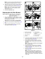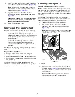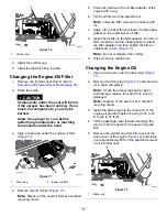
g032997
Figure 48
1.
Boom-section-bypass
adjustment knobs
2.
Boom-sections-bypass-shutoff
valve
10.
Turn on the left boom and turn off the right boom.
11.
Adjust the right boom-bypass knob (
until the pressure is at the previous level.
12.
Turn on the right boom and turn off the center
boom.
13.
Adjust the center boom-bypass knob (
until the pressure is at the previous level.
14.
Turn all the booms off.
15.
Turn the pump off.
Positioning the
Agitation-Bypass-Valve
Knob
•
The agitation-bypass valve is in the full O
PEN
position as shown in
•
The agitation-bypass valve is in the C
LOSE
(0)
position as shown in
•
The agitation-bypass valve is in an I
NTERMEDIATE
(adjusted relative to the pressure gauge for the
sprayer system) position as shown in
.
g028228
Figure 49
1.
Open
3.
Intermediate position
2.
Closed (0)
Calibrating the
Agitation-Bypass Valve
Service Interval:
Yearly—Calibrate the
agitation-bypass valve.
Important:
If you have the base Spray System
installed turn the power switch to the O
FF
position.
1.
Select an open, flat area to perform this
procedure.
2.
Fill the spray tank halfway with clean water.
3.
Verify the agitation-control valve is open.
Note:
If it has been adjusted, open it completely
at this time.
4.
Set the parking brake and start the engine.
5.
Set the pump switch and the agitation switch to
the O
N
position.
6.
Move the throttle lever to the F
AST
position.
7.
Turn the master-boom switch to the O
FF
position.
8.
Use the application-rate switch to adjust the
sprayer-system pressure to 689 kPa (100 psi).
9.
Turn the agitation switch to the O
FF
position and
read the pressure gauge.
•
If the pressure gauge indicates 689 kPa (100
psi), the agitation-bypass valve is properly
calibrated.
•
If the pressure gauge indicates differently,
continue to the next step.
10.
Adjust the agitation-bypass valve (
)
on the backside of the agitation valve until the
sprayer-system pressure is 689 kPa (100 psi).
g032532
Figure 50
1.
Actuator (agitation valve)
2.
Agitation-bypass valve
11.
Turn the pump switch to the O
FF
position.
12.
Move the throttle lever to the I
DLE
position and
turn the key switch to the O
FF
position.
44
Summary of Contents for Multi Pro 5800-D
Page 74: ...Spray System Schematic g034336 Figure 95 74 ...
Page 89: ...Notes ...
Page 90: ...Notes ...

