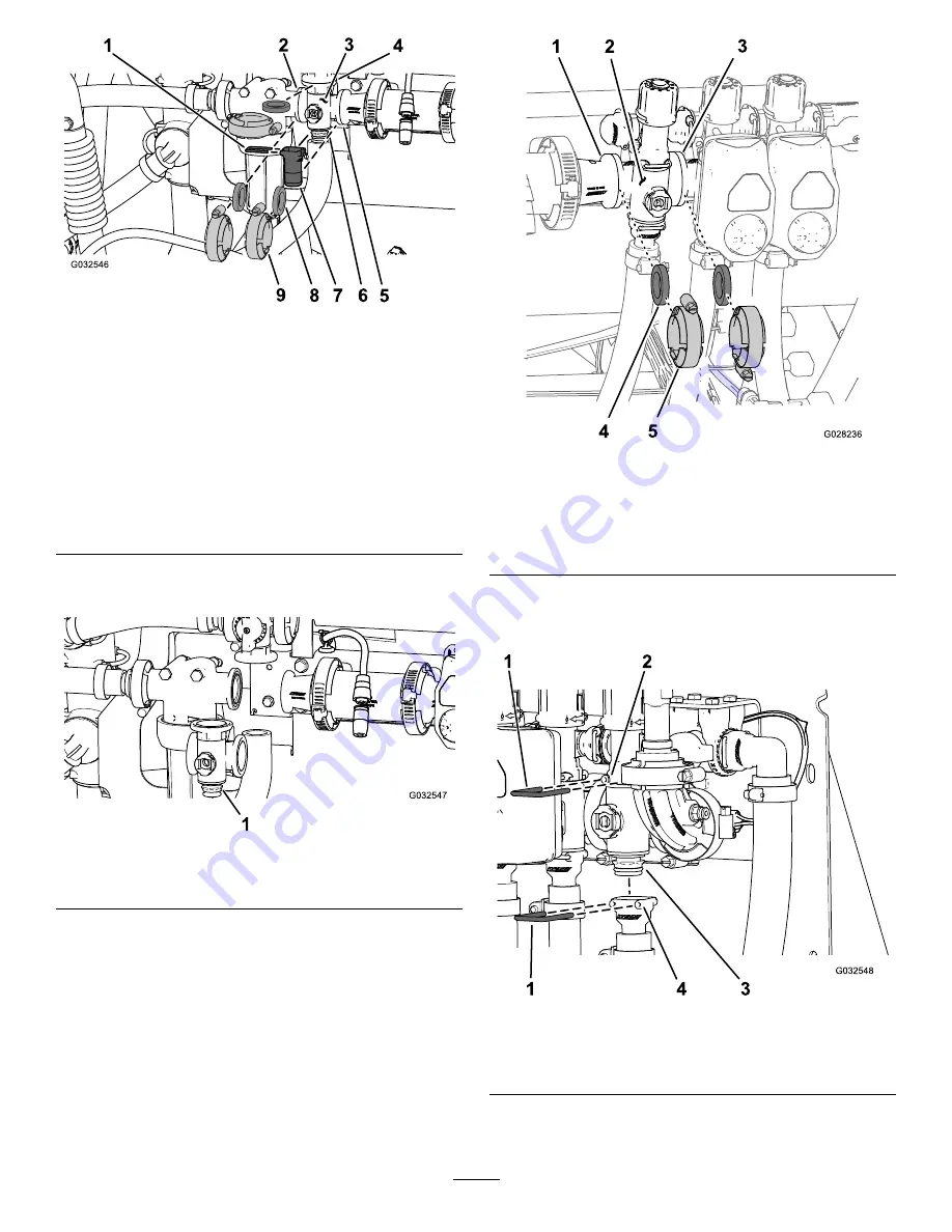
g032546
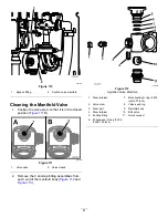
Figure 106
Agitation Valve
1.
Quick-connect pin
6.
Flange (adapter
fitting—agitation-throttle
valve)
2.
Flange (pressure-filter
head)
7.
Quick connect
3.
Manifold (agitation valve)
8.
Gasket
4.
Flange (agitation-bypass
valve)
9.
Flange clamp
5.
Flange (reducer coupling)
2.
Remove the agitation-valve manifold from the
machine (
).
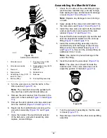
g032547
Figure 107
1.
Agitation-valve manifold
Removing the Section-Manifold
Valve
1.
Remove clamps and gaskets that secure the
manifold for the section valve (
) to
the adjacent section valve (if left, section valve
and reducer coupling).
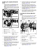
g028236
Figure 108
1.
Flange (reducer coupling)
4.
Gasket
2.
Manifold (section valve)
5.
Flange clamp
3.
Flange (adjacent section
valve)
2.
Remove the retainer that secures the
section-valve manifold to the bypass fitting
(
).
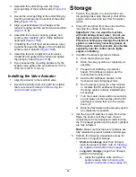
g032548
Figure 109
1.
Retainer
3.
Manifold-valve assembly
2.
Socket (bypass fitting)
4.
Socket (outlet fitting)
3.
Remove the section-valve manifold from the
machine (
).
80
Summary of Contents for Multi Pro 5800-D
Page 74: ...Spray System Schematic g034336 Figure 95 74 ...
Page 89: ...Notes ...
Page 90: ...Notes ...

