background image


2003—The Toro Company

8111 Lyndale Ave., Bloomington, MN 55420, USA

Printed in the USA

All Rights Reserved

Original Instructions (GB)

Light Kit

Power Max

 Snowthrowers with Alternator

Model No. 107-3827

Form No. 3351-124

Installation Instructions

Save these instructions with your Operator’s Manual for
future reference.

Contents of the Kit

DESCRIPTION

QUANTITY

Headlamp

1

Wire harness

1

U-clamp

1

Bracket

1

Washers

2

Nut, 5/16 in.

1

Locknuts, 1/4 in.

2

Serrated flange locknut

1

Plastic cable tie

1

Installing the Light Kit

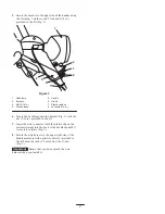
1. Secure the ring terminal of the wire harness to the

right rear engine mounting bolt with a serrated flange
locknut provided in the kit (Fig. 1).

1

2

3

5

4

6

Figure 1

1.

Right rear engine
mounting bolt

2.

Serrated flange locknut

3.

Ring terminal

4.

Alternator connector

5.

Wire harness connector

6.

Wire harness

Note: Position the ring terminal so that the wire
harness is routed toward the rear of the snowthrower
(Fig. 1).

2. Remove the rubber boot from the alternator connector

that hangs over the electric starter (Fig. 1).

3. Securely connect the wire harness connector to the

alternator connector (Fig. 1).

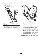
4. Secure the wire harness to the lower right side of the

handle assembly with a plastic cable tie (provided in
the kit) about an inch (2.5 cm) below the bottom end
of the upper handle (Fig. 2).

1

2

3

Figure 2

1.

Upper handle

2.

Wire harness

3.

Plastic cable tie

Summary of Contents for Power Max 107-3827

Page 1: ...r engine mounting bolt with a serrated flange locknut provided in the kit Fig 1 1 2 3 5 4 6 Figure 1 1 Right rear engine mounting bolt 2 Serrated flange locknut 3 Ring terminal 4 Alternator connector 5 Wire harness connector 6 Wire harness Note Position the ring terminal so that the wire harness is routed toward the rear of the snowthrower Fig 1 2 Remove the rubber boot from the alternator connect...

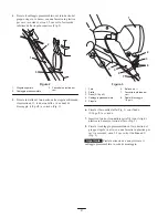
Page 2: ... 6 Secure the headlamp onto the bracket Fig 3 with the nut 5 16 in provided in the kit 7 Insert the wire connector with the plastic clip on the bottom straight into the back of the headlamp until it is securely in place Fig 3 8 Secure the wire harness to the upper right side of the handle assembly with a plastic cable tie provided in the kit about an inch 2 5 cm below the U bolt Fig 3 Important En...

Page 3: ...kte Bundmutter 1 Kunststoffkabelbinde 1 Installieren des Scheinwerfer Kits 1 Befestigen Sie den Ringpol des Kabelbaums mit einer gezackten Bundmutter aus dem Kit an der rechten hinteren Motorbefestigungsschraube Bild 1 1 2 3 5 4 6 Bild 1 1 Rechte hintere Motor befestigungsschraube 2 Gezackte Bundmutter 3 Ringpol 4 Lichtmaschinenanschluss 5 Kabelbaumanschluss 6 Kabelbaum Hinweis Positionieren Sie d...

Page 4: ... 4 5 6 7 8 Bild 3 1 Scheinwerfer 2 Halterung 3 Mutter 5 16 Zoll 4 Kabelbaum 5 Griff 6 U Schraube 7 Kunststoffkabelbinde 8 Sicherungsmutter 1 4 Zoll 6 Befestigen Sie den Scheinwerfer mit der Schraube 5 16 Zoll aus dem Kit an der Halterung Bild 3 7 Stecken Sie den Kabelstecker mit dem Kunststoffclip unten direkt hinten in den Scheinwerfer bis er ganz fest sitzt Bild 3 8 Befestigen Sie den Kabelbaum ...

Page 5: ...lastique 1 Installation du kit phare 1 Fixez la cosse en anneau du faisceau de câble au boulon de montage arrière droit du moteur au moyen d un contre écrou à collerette dentelée fourni avec le kit Fig 1 1 2 3 5 4 6 Figure 1 1 Boulon de montage arrière droit du moteur 2 Contre écrou à collerette dentelée 3 Cosse en anneau 4 Connecteur de l alternateur 5 Connecteur du faisceau de câblage 6 Faisceau...

Page 6: ...ig 3 1 2 3 4 5 6 7 8 Figure 3 1 Phare 2 Support 3 Écrou 5 16 pouce 4 Faisceau de câblage 5 Guidon 6 Boulon en U 7 Serre câble en plastique 8 Contre écrous 1 4 pouce 6 Fixez le phare au support Fig 3 avec l écrou 5 16 pouce fourni avec le kit 7 Insérez le connecteur du câble avec le serre câble en plastique en bas directement au dos du phare jusqu à ce qu il soit solidement fixé en position Fig 3 8...

Page 7: ...taggio del Kit faro 1 Fissate il morsetto a spina tonda del cablaggio preassemblato al bullone di fissaggio posteriore destro del motore utilizzando il dado di bloccaggio con flangia zigrinata a corredo Fig 1 1 2 3 5 4 6 Figura 1 1 Bullone di fissaggio posteriore destro del motore 2 Dado di bloccaggio con flangia zigrinata 3 Morsetto a spina tonda 4 Connettore dell alternatore 5 Connettore del cab...

Page 8: ...oll a corredo Fig 3 1 2 3 4 5 6 7 8 Figura 3 1 Faro 2 Staffa 3 Dado 5 16 poll 4 Cablaggio preassemblato 5 Stegola 6 Bullone ad U 7 Fascetta in plastica per cavi 8 Dadi di bloccaggio 1 4 poll 6 Fissate il faro sulla staffa Fig 3 con il dado 5 16 poll a corredo 7 Inserite a fondo il connettore serrafili con il clip di plastica in basso sul retro del faro Fig 3 8 Fissate il cablaggio preassemblato su...

Page 9: ...dningsfastspenneren til høyre monteringsbolt bak med en sagtakket låsemutter med flens som medfølger i settet fig 1 1 2 3 5 4 6 Figur 1 1 Høyre monteringsbolt bak 2 Sagtakket låsemutter med flens 3 Ringkobling 4 Generatorkopling 5 Ledningsfastspenner kobling 6 Ledningsfastspenner Obs Plasser ringkoblingen slik at ledningsfast spenneren ledes mot baksiden av snøfreseren fig 1 2 Fjern gummihetten fr...

Page 10: ...belsnor i plast 8 Låsemutre 1 4 tomme 6 Fest frontlyset i braketten fig 3 med mutteren 5 16 tomme som medfølger i settet 7 Før ledningskontakten med plastklemmen nederst rett inn bak i frontlyset til den sitter godt fast fig 3 8 Fest ledningsfastspenneren til høyre side øverst på håndtaket med kabelsnoren i plast medfølger i settet ca 2 5 cm under U bolten fig 3 Viktig Pass på at ledningsfastspenn...

Page 11: ... ringkoppling på den högra motorfästbulten bak med en räfflad låsmutter med fläns som medföljer i satsen fig 1 1 2 3 5 4 6 Figur 1 1 Höger motorfästbult bak 2 Räfflad låsmutter med fläns 3 Ringkoppling 4 Generatoranslutning 5 Ledningsnätanslutning 6 Ledningsnät Observera Placera ringkopplingen så att ledningsnätet är draget mot snöslungans bakre del fig 1 2 Ta bort gummiskon från generatoranslutni...

Page 12: ... 8 Låsmuttrar 1 4 6 Montera strålkastaren på fästet fig 3 med muttern 5 16 som medföljer i satsen 7 För in ledningsanslutningen med plastklämman i änden rakt in i strålkastarens baksida tills den sitter fast ordentligt fig 3 8 Montera ledningsnätet på den övre högra sidan av handtaget med ett kabelband i plast medföljer i satsen ca 2 5 cm under U bulten fig 3 Viktigt Kontrollera att du inte nyper ...

Page 13: ...sliitin moottorin oikean puoleiseen taka asennuspulttiin mukana toimitetulla hammastetulla laippalukkomutterilla kuva 1 1 2 3 5 4 6 Kuva 1 1 Moottorinoikeanpuoleinen taka asennuspultti 2 Hammastettu laippalukkomutteri 3 Rengasliitin 4 Laturin liitin 5 Johdinsarjan liitin 6 Johdinsarja Huomautus Sijoita rengasliitin siten että johdinsarja kulkee lumilingon takaosaan päin kuva 1 2 Irrota kumisuojus ...

Page 14: ... Muovinen nippuside 8 Lukkomutterit 1 4 6 Kiinnitä ajovalo kannattimeen kuva 3 mukana toimitetulla 5 16 tuuman mutterilla 7 Työnnä johdinliitintä jonka muovinipistin on alapäässä suoraan ajovalon takaosaan kunnes se on tiukasti paikallaan kuva 3 8 Kiinnitä johdinsarja oikean kahvan yläosaan muovisella nippusiteellä pakkauksessa noin 2 5 cm U pultin alapuolelle kuva 3 Tärkeää Varo että johdinsarja ...

Page 15: ......

Page 16: ......

Reviews: