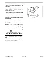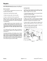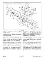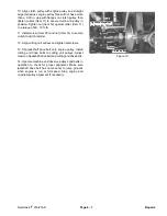
Cutting Unit Interlock Switch Replacement (Fig. 32, 33)
1. Raise cutting units and stop the engine. Engage the
parking brake. Raising the cutting units will take tension
off of the switch.
2. Remove the two wires that are connected to the
cutting unit interlock switch.
3. Loosen two (2) screws and remove the switch (lo
cated on left side of machine on bottom of hydraulic lift
cylinder.
3. Install new switch. DO NOT over-tighten screws as
the switch case could break.
1
NOTE: Apply “Loctite 271” or equivalent to threads of
Figure 32
switch screws before installing.
(Reelmaster 216)
4. Reconnect the two wires to the new switch. Make sure
1. Cutting unit interlock switch (Item 47)
that one wire is connected to the “COMMON” terminal,
1
and one wire is connected to the “NORMALLY OPEN”
(N.O.) terminal.
IMPORTANT: The cutting unit interlock switch has
three (3) terminals. If the two (2) wires are not con
nected to the “COMMON” and “NORMALLY OPEN”
(N.O.) terminals, the safety interlock circuit will not
function properly.
CAUTION
If the wires are not correctly installed to the
switch, the cutting units could engage when
Figure 33
in the raised position.
(Reelmaster 216-D)
1. Cutting unit interlock switch (Item 4)
5. Coat the switch terminals and wires with skin-over
grease.
Repairs
Page 6 - 34
Reelmaster
®
216/216-D
Summary of Contents for reelmaster 216
Page 2: ...This page is blank ...
Page 4: ...This page is blank ...
Page 8: ...Safety Instructions Page 1 4 Reelmaster 216 216 D ...
Page 12: ...Torque Specifications Page 2 4 Rev B Reelmaster 216 216 D ...
Page 26: ...Adjustments Page 4 4 Reelmaster 216 216 D ...
Page 40: ...Troubleshooting Page 5 14 Reelmaster 216 216 D ...
Page 42: ...Troubleshooting Page 5 16 Reelmaster 216 216 D ...
Page 72: ...Repairs Page 5 46 Reelmaster 216 216 D ...
Page 75: ...Reelmaster 216 S N 10001 19999 Reelmaster 216 216 D Page 6 3 Wiring Schematics ...
Page 76: ...Reelmaster 216 S N 20001 Up Wiring Schematics Page 6 4 Reelmaster 216 216 D ...
Page 77: ...Reelmaster 216 D Reelmaster 216 216 D Page 6 5 Wiring Schematics ...
Page 114: ...Repairs Page 7 8 Reelmaster 216 216 D ...
Page 124: ...Repairs Page 8 10 Reelmaster 216 216 D ...
Page 143: ...This page is blank ...


