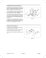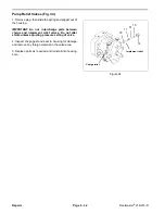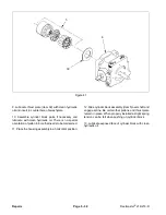
4. Gently slide the oiled seal retainer assembly (Item 15,
16, 17) over the shaft, chamfered side first, and press
into the body bore. When fully in place, the body snap
ring groove will be visible.
5. Install the snap ring (Item 14) into its body groove with
the snap ring’s sharp edges facing outward and the
retainer pin between the snap ring lugs, Be sure the
snap ring is completely seated in the groove.
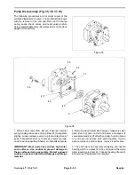
Disassembly of Cover Section of Motor
IMPORTANT: Before DISASSEMBLING the motor,
plug open ports and clean all dirt from the outside
of the motor.
1. Remove the key (Item 11) from the shaft.
2. Mount the motor in a vice or other holding device with
the shaft facing down.
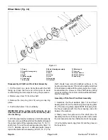
3. Remove the eight bolts (Item 1).
4. Remove the cover/bearing assembly (Item 2) and the
square ring seal (Item 4).
5. Remove the IGR set components (Item 5) starting
with the outer locating ring, rollers, outer rolls, inner rotor
and valve plate (Item 7). If any of these components are
damaged, the entire IGR assembly must be replaced.
6. Remove the two check balls (Item 6).
NOTE: The check balls may fall into the body tapered
holes or into the body valve ports during disassembly.
Be sure that the check balls are removed.
Disassembly of Shaft Section of Motor
(See Disassembly of Shaft and Front Seal Assembly
under Main Shaft Seal and/or Shaft Replacement.)
Assembly of Complete Motor
IMPORTANT: Before ASSEMBLING the motor,
lightly oil all seals, rollers and threaded bolt ends.
1. Before assembly, all parts must be clean free of nicks
and burrs. Wash parts in solvent. Dry parts with com
pressed air. Do not wipe them dry with a cloth or paper
as lint and dirt may remain.
2. Mount the body with the pilot and bearing facing up
in a vise or other holding mechanism.
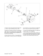
3. Insert the shaft (Figure 37, Item 10) and install seals
and thrust bearings. (See Assembly of Shaft and Front
Seal Assembly under Main Shaft Seal and/or Shaft
Replacement.)
4. Mount the body with the pilot and bearing facing down
in a vise or other holding fixture.
5. Put the rotary valve (Item 7) on the shaft spline with
“T” shaped slots on first.
6. Next put the IGR inner member on the shaft spline
with the semi-circular roll pockets between the rotary
valve ports. NOTE: This step “times” the motor for
rotation.
7. Put the contour member of the IGR over the inner and
insert seven rolls into the inner pockets (large diameter
rolls).
8. Lightly oil the square ring seal (Item 4) and put in the
body groove.
9. Put the check balls (Item 6) over the two 1/8" inch
diameter holes in the body. Be sure the check balls do
not fall into the body tapped holes.
10. Put the locating ring section (4.5 inch diameter) of
the IGR (Item 5) onto the body with the check ball holes
facing downward over the balls. Align the eight bolt
holes in the locating ring with the eight holes in the body.
The holes align in only one position.
NOTE: Be sure not to dislodge the body square ring seal
while moving the locating ring.
11. Install the eight locating ring rollers (small diameter
rolls) into their pockets and oil lightly.
12. Put the other lightly oiled square ring seal (Item 4)
into the groove in the cover and put the cover over the
shaft end and align the bolt holes.
13. Install the eight bolts with the lightly oiled thread
ends into the bolt holes and tighten diagonally to 30 ft-lb.
The motor is now ready for installation.
NOTE: The shaft may not turn freely after assembly. A
short running period may be required.
When installing the wheel hub onto the motor shaft,
tighten the castle nut (Item 13) to 80-90 ft-lb, then
continue tightening until the cotter pin slot lines up the
hole in the shaft.
Reelmaster
®
216/216-D
Page 5 - 41
Rev. A
Repairs
Summary of Contents for reelmaster 216
Page 2: ...This page is blank ...
Page 4: ...This page is blank ...
Page 8: ...Safety Instructions Page 1 4 Reelmaster 216 216 D ...
Page 12: ...Torque Specifications Page 2 4 Rev B Reelmaster 216 216 D ...
Page 26: ...Adjustments Page 4 4 Reelmaster 216 216 D ...
Page 40: ...Troubleshooting Page 5 14 Reelmaster 216 216 D ...
Page 42: ...Troubleshooting Page 5 16 Reelmaster 216 216 D ...
Page 72: ...Repairs Page 5 46 Reelmaster 216 216 D ...
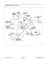
Page 75: ...Reelmaster 216 S N 10001 19999 Reelmaster 216 216 D Page 6 3 Wiring Schematics ...
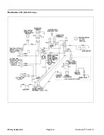
Page 76: ...Reelmaster 216 S N 20001 Up Wiring Schematics Page 6 4 Reelmaster 216 216 D ...
Page 77: ...Reelmaster 216 D Reelmaster 216 216 D Page 6 5 Wiring Schematics ...
Page 114: ...Repairs Page 7 8 Reelmaster 216 216 D ...
Page 124: ...Repairs Page 8 10 Reelmaster 216 216 D ...
Page 143: ...This page is blank ...


