background image

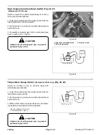
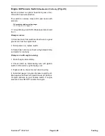
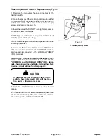
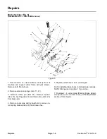
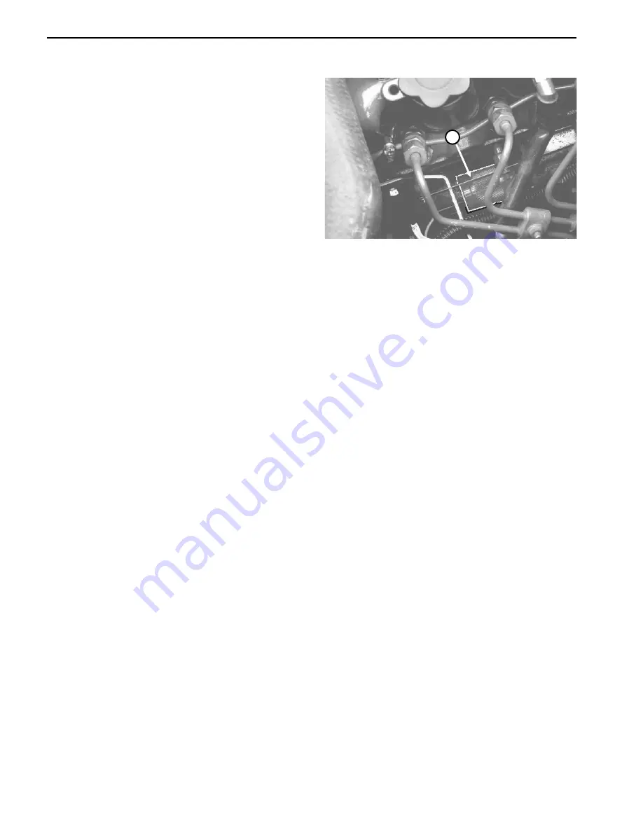
Injection Pump (ETR) Solenoid 

(Reelmaster 216-D only)

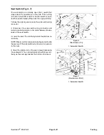
 (Fig. 19) 

The Reelmaster

®

 216-D has an energize-to-run (ETR) 

fuel stop solenoid mounted on the engine block next to 
the fuel injection pump with a purple wire attached. The 
solenoid will stop injector pump fuel delivery with any 
electrical failure in the RUN circuit. 

1. Disconnect the wire from the solenoid. 

2. Remove the solenoid from the injector pump. 

3. Connect a 12 volt battery so that a wire from positive 
(+) battery terminal is connected to switch terminal. 
Touch a wire from the negative (–) battery terminal to 
solenoid body. The plunger should retract. 

Figure 19 

NOTE: You can also test operation without removing the 
solenoid from the injector pump. Listen for an audible 

1. Fuel stop solenoid 

“click” as the solenoid extends and retracts while doing 
step 3 of the above procedure. This will not show if the 
solenoid is fully extending and retracting. 

Testing 

Page 6 - 26 

Reelmaster

® 

216/216-D 

Summary of Contents for reelmaster 216

Page 1: ...Serial Number of traction unit and cutting unit to The Toro Company 8111 Lyndale Avenue South Minneapolis MN 55420 The Toro Company reserves the right to change product specifications or this publication without notice see This safety symbol means DANGER WARN ING or CAUTION PERSONAL SAFETY IN STRUCTION When you this symbol carefully read the instructions that follow Failure to obey the instruction...

Page 2: ...This page is blank ...

Page 3: ...SERIES WORKSHOP MANUAL Chapter 5 Hydraulic System Specifications 5 2 General Information 5 3 Hydraulic Schematics 5 6 Special Tools 5 10 Troubleshooting 5 13 Testing 5 17 Adjustments 5 24 Repairs 5 29 Chapter 6 Electrical System Wiring Schematics 6 2 Special Tools 6 6 Troubleshooting Reelmaster 216 6 8 Troubleshooting Reelmaster 216 D 6 14 Testing 6 20 Repairs 6 31 Chapter 7 Wheels Brakes and Stee...

Page 4: ...This page is blank ...

Page 5: ...iar with the controls and know how to stop the machine and engine quickly Replacement Operator s Manuals are available by sending complete Model and Serial Number of traction unit and cutting units to The Toro Company 8111 Lyndale Avenue South Minneapolis MN 55420 Use the Model and Serial Number when referring to your machine If you have questions about this Service Infor mation please contact The...

Page 6: ... there is good artificial light B Drive slowly C Watch for holes or other hidden hazards D Look behind machine before backing up E Do not drive close to a sand trap ditch creek or other hazard F Reduce speed when making sharp turns and turning on a hillside G Avoid sudden stops and starts 16 Keep hands feet and clothing away from moving parts and reel discharge area If so equipped grass baskets mu...

Page 7: ...e re lieved by lowering cutting units to the ground and stop ping the engine 30 To reduce potential fire hazard keep engine area free of excessive grease grass leaves and dirt 31 If engine must be running to perform maintenance or an adjustment keep hands feet clothing and other parts of the body away from cutting units and other moving parts Keep all bystanders away 32 Do not overspeed engine by ...

Page 8: ...Safety Instructions Page 1 4 Reelmaster 216 216 D ...

Page 9: ...ngs and Torque Values Metric 3 Product Records Record information about your Reelmaster 216 216 D on the SERVICE HISTORY REPORT form Use this information when referring to your machine Product Records and Manuals MAINTENANCE CHARTS 4 Reelmaster 216 4 Reelmaster 216 D 5 Insert the Operator s Manuals and Parts Catalogs for your Reelmaster 216 216 D at the end of this section Reelmaster 216 216 D Pag...

Page 10: ...8 1 8 0 1250 3 175 5 8 0 6250 15 875 9 64 0 140625 3 572 41 64 0 640625 16 272 5 32 0 15625 3 969 21 32 0 65625 16 669 11 64 0 171875 4 366 43 64 0 671875 17 066 3 16 0 1875 4 762 11 16 0 6875 17 462 13 64 0 203125 5 159 45 64 0 703125 17 859 7 32 0 21875 5 556 23 32 0 71875 18 256 15 64 0 234375 5 953 47 64 0 734375 18 653 1 4 0 2500 6 350 3 4 0 7500 19 050 17 64 0 265625 6 747 49 64 0 765625 19 ...

Page 11: ...____________________________________________________________________________________________________ ________________________________________________________________________________________________________________________________________________________ __________________________________________________________________________________________________________________________________________________...

Page 12: ...Torque Specifications Page 2 4 Rev B Reelmaster 216 216 D ...

Page 13: ...RY REPORT for REELMASTER 216 TORO Model and Serial Number __________ __________ Engine Numbers ____________________ Transmission Numbers ____________________ Date Purchased ____________________ Warranty Expires __________ Purchased From ____________________ Contacts Parts Phone Service Phone Sales Phone See your TORO Distributor Dealer for other Publications Manuals and Videos from The TORO Compan...

Page 14: ...vel Torque Wheel Lug Nuts Service Replace Hydraulic Filter Adjust Electric Clutch D Level Inspect Traction Linkage Movement Service Change Hydraulic Fluid Decarbon Combustion Chamber Adjust Valves and Torque Head Bolts E Level Check Engine RPM idle and full throttle Service Initial break in at 5 hours Initial break in at 50 hours Replace Moving Hoses Replace Safety Switches Fuel Tank Drain Flush A...

Page 15: ...el Air Filter Pre Cleaner Clean Engine Cooling Fins Unusual Engine Noises Unusual Operating Noises Hydraulic System Oil Level Hydraulic Hoses for Damage Fluid Leaks Fuel Level Tire Pressure Instrument Operation Reel to Bedknife Adjustment Height of Cut Adjustment Cutting Unit Belt Adjustment Lubricate All Grease Fittings 1 Touch up damaged paint 1 Immediately after every washing regardless of the ...

Page 16: ...________________________ REELMASTER Date ______________ 216 Supervisor Maintenance Work Order duplicate this page for routine use Unit Designation TORO I D Remarks ____________ ____________ Service to perform circle A B C D E Other Technician A B C Check Battery Fluid Connections Check Traction Belt Tension Service Spark Plug Lubricate Grease Fittings Service Air Filter Paper Element Torque Wheel ...

Page 17: ...Y REPORT for REELMASTER 216 D TORO Model and Serial Number __________ __________ Engine Numbers ____________________ Transmission Numbers ____________________ Date Purchased ____________________ Warranty Expires__________ Purchased From ____________________ Contacts Parts Phone Service Phone Sales Phone See your TORO Distributor Dealer for other Publications Manuals and Videos from The TORO Compan...

Page 18: ...ter Separator Replace Hydraulic Filter C Level Torque Wheel Lug Nuts Service Replace Hydraulic Fluid Check Battery Level Connections Inspect Traction Linkage Movement Torque Head Bolts and Adjust Valves D Level Check Engine RPM idle and full throttle Service Initial break in at 10 hours Initial break in at 50 hours Replace Moving Hoses Replace Safety Switches Annual Recommendations Items listed ar...

Page 19: ...ilter Dust Cup Baffle Radiator Screen for Debris Unusual Engine Noises 1 Unusual Operating Noises Hydraulic System Oil Level Hydraulic Hoses for Damage Fluid Leaks Fuel Level Tire Pressure Instrument Operation Reel to Bedknife Adjustment Height of Cut Adjustment Cutting Unit Belt Adjustment Lubricate All Grease Fittings 2 Touch up damaged paint 1 Check glow plug and injector nozzles if hard starti...

Page 20: ..._____________ REELMASTER 216 D Supervisor Maintenance Work Order Date ______________ duplicate this page for routine use Unit Designation TORO I D Remarks ____________ ____________ Service to perform circle A B C D Other Technician A Service every 50 hours B Service every 100 hours C Service every 200 hours Inspect Air Filter Dust Cup and Baffle Change Engine Oil Filter Service Air Filter Lubricat...

Page 21: ..._____________________________________________________________________________________________________________________________ ________________________________________________________________________________________________________________________________________________________ Chapter 3 Kohler Engine Table of Contents SPECIFICATIONS 1 ADJUSTMENTS 2 Carburetor Adjustments 2 KOHLER MAGNUM ENGINE SE...

Page 22: ...tion and cutting units are on the shop floor Also engage parking brake IMPORTANT Do not close the screw too tightly CAUTION because the screw will likely be damaged Note These settings are approximate however the settings will allow engine to be starter so carburetor can be fine tuned steps 4 7 4 Start engine and let it run for 5 to 10 minutes at half throttle to warm up Engine must be warm before...

Page 23: ...___________________ ________________________________________________________________________________________________________________________________________________________ ________________________________________________________________________________________________________________________________________________________ __________________________________________________________________________...

Page 24: ...raise hood 2 Open fuel shut off valve under fuel tank and on fuel filter 3 Open two 2 bleed screws on side of fuel filter mounting head allowing bowl to re fill with fuel Close bleed screws when bowl is filled 4 On left side of engine below alternator locate trans fer pump inlet screw Note angle of fitting on transfer pump inlet and loosen screw left screw only 5 When a steady stream of fuel flows...

Page 25: ... position Loosen capscrew and nut securing throttle cable clamp near engine Pull cable toward frame until throttle lever on engine is up against high speed adjustment screw Tighten capscrew and nut securing throttle cable clamp 5 Check to make sure throttle lever on engine goes against high speed adjustment screw when throttle on control panel is moved up to high speed position When throttle lever...

Page 26: ...Adjustments Page 4 4 Reelmaster 216 216 D ...

Page 27: ...draulic Oil Reservoir Plug 12 Charge Pump 30 TROUBLESHOOTING 13 Pump Shaft and Trunnion Seal Replacement 31 System Operates Hot 14 Pump Check Valves 31 Loss of Power or Pump Relief Valves 32 Unit Will Not Operate in Either Direction 15 Pump Disassembly 33 Cutting Units Do Not Lift or Lift Slowly 16 Assembly of Pump 36 TESTING 17 Wheel Motor 40 Test Hook up No 1 Charge Pump Flow and Lift Control Va...

Page 28: ..._____ Specifications Item Description Pump Fig 1 Sauer Sundstrand variable axial piston pump Charge pressure 70 150 PSI Implement relief pressure 700 800 PSI Wheel Motors Nichols Gray orbit rotor type Lift Control Valve Spool type directional control valve Hydraulic Filter Spin on cartridge type 25 micron Hydraulic Oil Mobil DTE 26 or equivalent Reservoir Reelmaster 216 Fig 2 Approximately 3 5 gal...

Page 29: ...n on the face seal end of the fitting and tighten the nut until finger tight 5 Mark the nut and fitting body Hold the body with a wrench Use another wrench to tighten the nut to the correct flats from finger tight F F F T The markings on the nut and fitting body will verify that the connection has been tightened Size F F F T 4 1 4 in nominal hose or tubing 75 25 6 3 8 in 75 25 8 1 2 in 75 25 10 5 ...

Page 30: ...or any foreign material 2 Always replace the O ring seal when this type of fitting shows signs of leakage Lock Nut 3 Lubricate the O ring with a light coating of oil Back Up Washer 4 Turn back the jam nut as far as possible Make sure O Ring the back up washer is not loose and is pushed up as far as possible Step 1 5 Install the fitting into the port and tighten finger tight Figure 7 until the wash...

Page 31: ...may be damaged If machine must be towed a longer distance trans port it on a truck or trailer 1 To tow machine rotate by pass valve on pump coun terclockwise until it is fully open 2 Before starting engine close by pass valve securely by rotating it clockwise Do not exceed 5 to 8 ft lb of torque Do not start engine while valve is open Figure 9 1 Reelmaster 216 D shown 1 By pass valve Reelmaster 21...

Page 32: ...Y PASS VALVE TOP A CHARGE CHECK CHARGE CHECK VALVE VALVE PILOT OPERATED VALVE LIFT CYLINDER RESERVOIR IMPLEMENT CHARGE RELIEF RELIEF VALVE VALVE CHARGE PUMP BOTTOM B 3 2 1 4 8 5 FILTER VARIABLE DISPLACEMENT PUMP COOLER B A PUMP WHEEL MOTOR LEFT OUT IN Hydraulic Schematic Reelmaster 216 Page 5 6 Reelmaster 216 216 D ...

Page 33: ...VE OUT M CHARGE CHECK TOP CHARGE CHECK TO 6 VALVE VALVE BOT 5 B UPPER A LOWER 7 PILOT OPERATED 8 VALVE 4 LIFT CYLINDER REVERSE FORWARD IMPLEMENT CHARGE RESERVOIR RELIEF VALVE RELIEF VALVE WHEEL MOTOR REAR CHARGE PUMP 1 FILTER VARIABLE 2 DISPLACEMENT PUMP 3 COOLER PUMP WHEEL MOTOR REAR LEFT Reelmaster 216 216 D Page 5 7 Hydraulic Schematic Reelmaster 216 3WD ...

Page 34: ...TOM OUT CHARGE CHECK CHARGE CHECK 6 VALVE VALVE 5 B UPPER A LOWER 7 8 BOTTOM FRONT 4 LIFT CYLINDER IMPLEMENT RELIEF VALVE CHARGE RELIEF VALVE RESERVOIR FILTER REVERSE FORWARD CHARGE PUMP 1 DISPLACEMENT VARIABLE TOP FRONT 3 PUMP 2 COOLER PUMP WHEEL MOTOR LEFT Hydraulic Schematic Reelmaster 216 D Page 5 8 Reelmaster 216 216 D ...

Page 35: ...Hydraulic Schematic Reelmaster 216 D 3WD Reelmaster 216 216 D Page 5 9 Rev A Hydraulic Schematic Reelmaster 216 D 3WD ...

Page 36: ...supplier Hydraulic Pressure Test Kit Fig 10 Used to take various pressure readings for diagnostic tests Quick disconnect fittings provided attach directly to mating fittings on machine test ports if equipped without tools A high pressure hose is provided for remote readings Contains one each 1000 5000 and 10000 PSI gauges Use gauges as recommended in Testing section of this chapter Figure 10 Speci...

Page 37: ...working load is created in the circuit 3 LOW PRESSURE GAUGE Low range gauge to provide accurate reading at low pressure 0 1000 PSI This gauge has a protector valve which cuts out when pressure is about to exceed the normal range for the gauge The cutout pressure is adjustable 4 HIGH PRESSURE GAUGE High range gauge to accommodate pressure beyond the capacity of the low pressure gauge 0 5000 PSI 5 F...

Page 38: ... Oil Reservoir Plug Fig 13 Used to temporarily plug the outlet of the hydraulic tank to retain most of the fluid when the hydraulic filter is removed Figure 13 Special Tools Page 5 12 Rev A Reelmaster 216 216 D ...

Page 39: ...ine locate the cause of the trouble and correct it before allowing the machine to be used again Continued use of an improperly functioning hydraulic system could lead to extensive internal component damage The charts that follow contain detailed information to assist in troubleshooting There may possibly be more than one cause for a machine malfunction All causes should be checked in the order in ...

Page 40: ...Troubleshooting Page 5 14 Reelmaster 216 216 D ...

Page 41: ...NOTE Before checking for problems in hydrau lic system make sure brakes are released Check for debris in brakes Reelmaster 216 216 D Page 5 15 Troubleshooting ...

Page 42: ...Troubleshooting Page 5 16 Reelmaster 216 216 D ...

Page 43: ...ly removed within a few hours by a doctor familiar with this type of injury or gan grene may result WARNING 1 Thoroughly clean the machine before disconnecting or disassembling any hydraulic components Always keep in mind the need for cleanliness when working on hydraulic equipment 2 Put caps or plugs on any hydraulic lines left open or exposed during testing or removal of components 3 The engine ...

Page 44: ...harge Pump Flow and Implement Relief Pressure Figure 14 1 Operate engine at full speed Reelmaster 216 valve connections Reelmaster 216 3600 100 RPM Reelmaster 216 D 3200 100 RPM 2 Make sure hydraulic oil is at operating temperature 3 Traction pedal and lift valve in neutral Parking brake engaged 4 While watching flow and pressure gauges slowly close flow control valve until flow gauge reads 1 GPM ...

Page 45: ...ON NOTE For traction system tests attach log chain to rear frame and then to something solid in shop TEST A Traction Pump Flow 1 Make sure hydraulic oil is at operating temperature 2 Block up one front traction wheel off floor Place blocks in front of remaining wheels 3 Operate engine at full speed Reelmaster 216 3600 100 RPM Reelmaster 216 D 3200 100 RPM 4 While watching flow and pressure gauges ...

Page 46: ...or from rear motor B For internal motor drag If internal drag remove motor and repair as necessary 6 Repeat steps 1 5 for other wheel s 1 Make sure hydraulic oil is at operating temperature 2 All wheels on floor 3 Block front of all wheels 4 Operate engine at full speed Reelmaster 216 3600 100 RPM Reelmaster 216 D 3200 100 RPM 5 While watching pressure gauges slowly push traction pedal into forwar...

Page 47: ...ment Relief Pressure 1 Make sure hydraulic oil is at operating temperature 2 Operate engine at full speed Reelmaster 216 3600 100 RPM Figure 20 Reelmaster 216 D 3200 100 RPM 1 1000 PSI hydraulic pressure gauge 3 Traction pedal in neutral and parking brake engaged 4 Pull lift valve lever to raise cutting units and hold lever so systems goes over relief TESTER READINGS 700 800 PSI Implement relief p...

Page 48: ...M Reelmaster 216 D 3200 100 RPM 4 Attach a heavy chain to rear frame of machine and then to something solid in shop Engage parking brake CAUTION Keep everyone clear from the front of unit during traction system tests Operator must be on seat or the safety interlock will stop the engine when the traction pedal is depressed Figure 21 1 1 10 000 PSI hydraulic pressure gauge 5 While watching pressure ...

Page 49: ...ed Reelmaster 216 3600 100 RPM Reelmaster 216 D 3200 100 RPM Figure 22 1 2 4 Attach a heavy chain to rear frame of machine and 1 Forward traction test port then to something solid in shop Engage parking brake 2 Reverse traction test port Keep everyone clear from the front of unit during traction system tests Operator must be on seat or the safety interlock will stop the engine when the traction pe...

Page 50: ...unterclockwise as viewed while facing pump plate Lightly tap pump plate clock wise if wheel is rotating backward When wheel stops rotating tighten capscrews holding pump plate against side of pump Verify the adjustment with throttle in SLOW and FAST position 3 Should the wheel continue to rotate check for the following A Ball bearing is loose or worn out B Plunger on interlock switch is sticking C...

Page 51: ... pump plate counterclockwise as viewed Figure 24 while facing pump plate Lightly tap pump plate clock wise if wheel is rotating backward When wheel stops 1 Right fender rotating tighten capscrews holding pump plate against 2 Fender mounting screws 2 1 side of pump Verify the adjustment with throttle in SLOW and FAST position 4 Should the wheel continue to rotate check for the following A Ball bear...

Page 52: ...ping screws securing support screen to hydraulic support panel Remove screen 2 Loosen jam nuts on each end of traction rod 3 Rotate rod to get a dimension of 3 8 inch between traction pedal shaft and R H footrest when pedal is pushed fully forward Figure 26 4 Re tighten jam nuts securing traction rod and reinstall 1 Support screen support screen 5 The stop for reverse travel under pedal may be adj...

Page 53: ...ove 4 screws securing right fender Fig 58 to frame and remove fender 2 Loosen jam nuts on each end of traction rod 3 Rotate rod until required to get a dimension of 1 16 inch between pedal stop cam and R H footrest when pedal is pushed fully forward 4 Re tighten jam nuts securing traction rod adjustment 5 The stop for reverse travel under pedal may be adjusted for slower travel Speeds in excess of...

Page 54: ...n span of belt Check tension again on new belts after 8 hours of operation Tighten nut on adjustment rod until desired belt tension is attained Belt should be tightened to 140 lbs of tension NOTE Tighten belt to eliminate slippage squeeling under load but do not overtighten Figure 30 1 Nut 2 Adjustment rod Adjustments Page 5 28 Reelmaster 216 216 D ...

Page 55: ...airs check control linkage for proper adjust ment binding or broken parts 3 If a pump was disconnected or removed prime system before operating Disconnect fuel stop solenoid electrical connector on diesel engine or disconnect ig nition wires on gasoline engine Turn ignition switch to engage starter for five 5 seconds to prime pump Repeat cranking procedure again Connect injection pump fuel stop so...

Page 56: ...tching or heavy wear patterns Replace both parts of this cartridge if necessary Do not replace or interchange individual parts within the cartridge The drive pin should always be replaced 6 Visually inspect bearing Item 22 O ring Item 27 and shaft seal Item 23 and replace as required 7 Coat both sides of pump cartridge Item 25 and housing face with hydraulic oil Install drive pin Item 26 into hole...

Page 57: ...raulic oil to insure that the seal is not damaged during assemb ly Slide the seal over the shaft and press it into the housing bore 3 To service the trunnion shaft seals it is necessary that the retaining rings Item 13 and washers Item 11 be removed before removing the seals The washer should be replaced if it is noticeably bent or distorted Pump Check Valves Fig 33 1 Remove plug Item 50 then slid...

Page 58: ...nd implement relief valves Do not alter shims unless adjusting pressure setting of valve 2 Inspect the poppet and seat in housing for damage and remove any foreign material in the valve area 3 Replace parts as required and reinstall into housing bore 14 15 51 17 18 Implement relief Charge relief Figure 34 Repairs Page 5 32 Reelmaster 216 216 D ...

Page 59: ...tly Loosen screws evenly to prevent distortion of valve plate tends to lift off with end cap hold it in place parts If separation does not occur as screws are loos on end cap and remove both parts together If valve ened tap end cap with soft hammer until parts separate plate remains on cylinder block remove it at this time IMPORTANT Most parts have critical high toler 3 The end cap is an assembly ...

Page 60: ... orientation of piston to bore that needs to be are free in bores maintained Do not attempt to disassemble the spring and other parts from the center bore of the cylinder 6 Remove thrust plate Item 39 from counterbore in block The entire cylinder block assembly Item 5 face of swashplate Item 37 Visually inspect both sides should be replaced if any of its components are dam for damage and flatness ...

Page 61: ...and control shafts 9 Drive each trunnion shaft out of swashplate bore toward outside of housing Once clear of swashplate bore the shaft can be removed easily The swashplate Item 37 is then removed from the pump housing 10 Inspect the needle bearings Item 9 If replacement is required press out the old bearings 11 Remove retaining ring Item 36 from housing then press out shaft and bearing assembly I...

Page 62: ... from damage and foreign material 2 Assemble shaft Item 6 bearing Item 35 and retain ing ring Item 34 then press into housing Item 8 Install retaining ring Item 36 in groove in housing 3 Place housing Item 8 with large cavity up Use care not to scratch the port face surface 4 Press needle bearings Item 9 into each side of housing until flush to 1 64 inch below counterbore for lip seals 5 Place swa...

Page 63: ...ontrol shaft Item 28 installing first pin housing to 150 each side of center until second pin can be started then driving in both pins together until the last pin is 1 4 inch below swashplate 7 Install one 1 pin in trunnion shaft Item 12 driving it in until it is 1 4 inch below swashplate Reelmaster 216 216 D Page 5 37 Repairs ...

Page 64: ...ain in place When properly installed a slight spring 10 Assemble cylinder block parts if necessary and tension can be felt when pushing on cylinder block lubricate with clean hydraulic oil There is no special orientation of piston to bore that needs to be maintained 13 Lubricate exposed face of cylinder block with clean hydraulic oil 11 Place the housing assembly in a horizontal position Repairs P...

Page 65: ...lip it over the pin and protruding bearing 17 Place the gasket Item 42 on housing Item 8 then install end cap and valve plate Hold the valve plate so it does not drop off during assembly 18 Install four 4 screws Item 46 and tighten alter nately until the end cap and housing are pulled com pletely together Torque to 27 37 ft lbs Check for proper internal assembly by slowly rotating pump and control...

Page 66: ...the various parts of the seal assembly Item 15 16 17 shaft Item 10 and thrust bearing assembly Item 19 20 21 Replace any worn or damaged parts Always replace the seal retainer assembly Item 15 16 17 The shaft should have smooth polished surfaces in the bearing and seal areas If the shaft is lightly scratched in these areas polish with fine emery paper in a circum ferential direction However if the...

Page 67: ...ism 3 Insert the shaft Figure 37 Item 10 and install seals and thrust bearings See Assembly of Shaft and Front Seal Assembly under Main Shaft Seal and or Shaft Replacement 4 Mount the body with the pilot and bearing facing down in a vise or other holding fixture 5 Put the rotary valve Item 7 on the shaft spline with T shaped slots on first 6 Next put the IGR inner member on the shaft spline with t...

Page 68: ... Carefully push and twist control valve spool to remove it from valve body Set spool assembly aside 7 Use a hooked scribe or thin screwdriver to remove O rings Item 9 from inside bore of valve body be careful not to scratch valve bore finish 8 Inspect all components of control valve assembly for wear paying special attention to valve spool Signs of wear on one side of spool may indicate a bent spo...

Page 69: ...ide of cylinder IMPORTANT To prevent damage when clamping cylinder barrel in a vise clamp only on pivot end 3 Mount cylinder in a vise so shaft end of cylinder is tilted up slightly Do not close vise so firmly that the barrel could become distorted 4 Use a spanner wrench to rotate head Item 3 and remove retaining ring Item 12 Figure 46 Retaining ring Spanner wrench Removing retaining ring Reelmast...

Page 70: ...for evidence of excessive scoring pitting or wear Replace any defective parts 10 Use new seals Items 1 2 7 9 11 13 when reassembling Put a light coating of hydraulic oil on all new seals and back up washers Install the new seals and back up washers Install head Item 3 onto shaft Item 4 Install piston Item 8 onto shaft and tighten lock nut Item 5 11 Put a light coating of hydraulic oil on all cylin...

Page 71: ...to remove back up washers Item 6 and O rings Item 7 from inside bore of valve body be careful not to scratch valve bore finish 8 Inspect all components of control valve assembly for wear paying special attention to valve spool Signs of wear on one side of spool may indicate a bent spool Inspect spool for flatness and replace it if necessary 9 Wash parts in solvent Dry parts with compressed air Do ...

Page 72: ...Repairs Page 5 46 Reelmaster 216 216 D ...

Page 73: ...20 Seat Switch 21 Traction Neutral Switch 22 Cutting Unit Interlock Switch 22 Cutting Unit Clutch Reel Drive Switch 23 Start and High Temp Relays Reelmaster 216 D only 24 Glow Plugs Reelmaster 216 D only 25 Battery 25 Injection Pump ETR Solenoid Reelmaster 216 D only 26 Indicator Lights and Gauges 27 High Temperature Shut Down Switch Reelmaster 216 D only 28 Temperature Gauge Sender Reelmaster 216...

Page 74: ...Wiring Schematics Reelmaster 216 S N 99999 Below Wiring Schematics Page 6 2 Reelmaster 216 216 D ...

Page 75: ...Reelmaster 216 S N 10001 19999 Reelmaster 216 216 D Page 6 3 Wiring Schematics ...

Page 76: ...Reelmaster 216 S N 20001 Up Wiring Schematics Page 6 4 Reelmaster 216 216 D ...

Page 77: ...Reelmaster 216 D Reelmaster 216 216 D Page 6 5 Wiring Schematics ...

Page 78: ...om a local supplier Continuity Tester Battery powered test lamp which is helpful in testing for continuity of circuits and electrical components when the current is off Volt Ohm Amp Meter The meter can test electrical components and circuits for current resistance or voltage draw Figure 1 Figure 2 Special Tools Page 6 6 Reelmaster 216 216 D ...

Page 79: ...Skin Over Grease Special non conductive grease which forms a light pro tective skin to help waterproof electrical switches and contacts Figure 3 Reelmaster 216 216 D Page 6 7 Special Tools ...

Page 80: ... that area repairing one component at a time Attempting to repair more than one system at one time will lead to confusion Possible Causes and Corrections in the troubleshooting charts should be checked in the order in which they are listed If the machine being repaired has any interlock switches by passed they must be reconnected for proper trou bleshooting and safety Condition Possible Cause Corr...

Page 81: ... corroded or damaged Ignition switch faulty Ignition switch wiring loose cor roded or damaged Starter solenoid faulty Starter solenoid wires loose cor roded or damaged Charge battery Replace battery if it will not hold a charge Clean and tighten or repair as necessary Check fuse and replace if fuse is open If fuse burns out often find and correct cause Test switch and replace if faulty Make sure w...

Page 82: ...on Possible Cause Correction Engine cranks but does not start Engine wiring connector or wires Repair wiring loose corroded or damaged Engine engine ignition or fuel sys See Troubleshooting section of tem problem Kohler Magnum Engine Service Manual Interlock module faulty Replace interlock module Engine cranks but should not Traction neutral switch out of ad Test switch and replace if faulty with ...

Page 83: ...seat Seat switch faulty or out of adjust Test seat switch Adjust or re ment place if faulty Traction neutral switch faulty or out Test switch Adjust or replace if of adjustment fautly Check for correct terminal connections Interlock module faulty Replace interlock module Engine kills when traction pedal Operator sitting too far forward on Instruct operator is depressed or cutting unit clutch seat ...

Page 84: ...faulty or out of adjust Test seat switch Adjust or re ment place if faulty Interlock module faulty Interlock module faulty Cutting units run but should not Cutting unit interlock switch faulty Test switch and replace if faulty when raised but shut off with cut Make sure wires are connected ting unit engage switch to COMMON and NORMALLY OPEN N O terminals Cutting units shut off when Cutting unit en...

Page 85: ...gine If engine cranks there may be a malfunction in interlock system Repair immedi ately If engine does not crank proceed to step 3 3 Sit on seat Depress traction pedal in forward and reverse directions while trying to start engine If engine cranks while pedal is in forward or reverse position there may be a malfunction in interlock system Repair immediately If engine does not crank proceed to ste...

Page 86: ...hen check that area repairing one component at a time Attempting to repair more than one system at one time will lead to confusion Possible Causes and Corrections in the troubleshooting charts should be checked in the order in which they are listed If the machine being repaired has any interlock switches by passed they must be reconnected for proper trou bleshooting and safety Condition Possible C...

Page 87: ...tion switch faulty Ignition switch wiring loose cor roded or damaged Start relay faulty Start relay wires loose corroded or damaged Starter solenoid wiring loose cor roded or damaged Starter solenoid faulty Charge battery Replace battery if it will not hold a charge Clean and tighten or repair as necessary Check fuse and replace if fuse is open If fuse burns out often find and correct cause Replac...

Page 88: ...ction pump ETR solenoid faulty Test solenoid Replace if faulty Glow glow plug wiring loose cor Repair wiring roded or damaged Glow plugs faulty Test glow plugs and replace if faulty Engine or fuel system problem See Troubleshooting section of Perkins Engine Workshop Man ual Engine cranks but should not Traction neutral switch out of ad Test switch and replace if faulty with traction pedal out of n...

Page 89: ...essed with no operator on down position seat Check for binding seat pivot hinge Check for waterlogged seat Seat switch faulty or out of adjust Test seat switch Adjust or re ment place if faulty Engine kills when traction pedal Operator sitting too far forward on Instruct operator is depressed or cutting unit clutch seat seat switch not depressed switch is turned ON Seat hinge support pin or spring...

Page 90: ...r out of adjust ment Test seat switch Adjust or re place if faulty Cutting units run but should not Cutting unit interlock switch faulty Test switch and replace if faulty when raised but shut off with cut Make sure wires are connected ting unit clutch switch to COMMON and NORMALLY OPEN N O terminals Cutting units shut off when Cutting unit clutch switch faulty Test switch Replace if faulty raised ...

Page 91: ...ine If engine cranks there may be a malfunction in interlock system Repair immedi ately If engine does not crank proceed to step 3 3 Sit on seat Depress traction pedal in forward and reverse directions while trying to start engine If engine cranks while pedal is in forward or reverse position there may be a malfunction in interlock system Repair immediately If engine does not crank proceed to step...

Page 92: ...esting electrical components for con tinuity with a volt ohm meter or continuity tester make sure that power to the circuit has been disconnected CAUTION Ignition Key Switch The circuitry of the ignition switch is shown in the charts With the use of a continuity tester the switch functions may be tested to determine whether all circuits are being completed while the key is moved to each position P...

Page 93: ...ll a continuity tester or ohm meter between the two leads of the seat switch 3 Lower the seat The continuity tester should show no continuity NOTE Make sure the compression spring and pin holds the seat up off the seat switch when there is no operator on the seat 4 Have the operator sit on the seat slowly depressing the seat switch The continuity tester should show con tinuity as the seat approach...

Page 94: ...Interlock Switch Fig 9 10 The cutting unit interlock switch is normally open and closes with the lift cylinder is retracted cutting units lowered IMPORTANT The traction switch has three 3 ter minals Make sure the wires are connected to the COMMON and N O terminals Test the switch by disconnecting the wires from the switch terminals and connecting a continuity tester across the COMMON and N O termi...

Page 95: ... and B E should show continuity Reelmaster 216 S N 20001 and up Reelmaster 216 D To test switch independent of wiring harness discon nect wire connector s from switch terminals When the switch is ON Engage there should be continuity be tween terminals 5 6 only When the switch is OFF Disengage terminals 1 2 and 4 5 should show continuity 1 Figure 11 Reelmaster 216 1 Cutting unit clutch Reel switch ...

Page 96: ...ty tester between the relay termi nals terminals 30 and 87 The relay should make and break continuity at terminals 30 and 87 as 12 V D C is connected and disconnected to terminal 85 with termi nal 86 connected to ground 1 Figure 13 1 Start relay Item 39 1 Figure 14 1 High temp relay Item 34 Figure 15 Testing Page 6 24 Reelmaster 216 216 D ...

Page 97: ...nd ground Resistance should be 1 6 0 16 OHM Resistance of 0 indicates a short circuit Battery Fig 17 18 Use a hydrometer to test the battery Charge the battery if necessary see Battery Service Electrolyte specific gravity Fully charged 1 250 1 280 Discharged less than 1 240 Figure 17 Reelmaster 216 1 Battery 1 Figure 18 Reelmaster 216 D 1 Battery Reelmaster 216 216 D Page 6 25 Testing ...

Page 98: ... solenoid from the injector pump 3 Connect a 12 volt battery so that a wire from positive battery terminal is connected to switch terminal Touch a wire from the negative battery terminal to solenoid body The plunger should retract 1 Figure 19 NOTE You can also test operation without removing the solenoid from the injector pump Listen for an audible 1 Fuel stop solenoid click as the solenoid extend...

Page 99: ...inals Temperature Light Reelmaster 216 D only The temperature light should come on only if the high temperature shut down switch and relay has stopped the engine coolant temperature above 221o F 105o C Test the lamp and relay by disconnecting the wire from high temperature shut down switch and grounding it against the engine The light should come on when the wire is grounded with the ignition swit...

Page 100: ...tch 2 Temp gauge sender Handle hot oil with special care to prevent personal injury or fire Figure 21 Temperature Gauge Sender Reelmaster 216 D only Fig 20 22 Switch is located on top of cylinder head with white black wire attached 1 Lower the coolant level in the engine and remove the temperature gauge sender 2 Put the switch in a container of oil with a thermometer and heat the oil 3 With an Ohm...

Page 101: ...und such as the engine block 2 If lamp comes on replace switch 3 If lamp does not come on check wiring between lamp and switch for continuity If lamp is on with engine running 1 Shut off engine immediately 2 Check switch by disconnecting wire with ignition switch in ON position Light should go out 3 If light is still on check for short circuit in wiring 4 Install test gauge in engine oil pressure ...

Page 102: ...h connector terminals The clutch should engage as 12 VDC is connected to the clutch connector terminals Interlock Module Reelmaster 216 only Fig 27 The interlock module senses the condition of the seat switch traction neutral switch and cutting unit clutch reel engage switch Fig 12 The seat switch must remain CLOSED while the traction switch or cutting unit clutch switch is OPEN or the engine will...

Page 103: ... the level is to the bottom of the cap tubes If the level is below the plates add water only until the plates are covered and then charge the battery After charging fill the battery to the proper level Electrolyte Specific Gravity Reelmaster 216 Battery Specifications BCI Group U1 Battery 200 Amp Cranking Performance at 0o F 17 o C 32 min Reserve Capacity at 80o F 27 o C Reelmaster 216 D Battery S...

Page 104: ... system is protected by a 15A ACC fuse located on the dash panel a 15A ENGINE fuse in the wiring harness near the ignition switch and a fusible link in the wiring harness near the starter solenoid 1 Figure 29 Reelmaster 216 1 Fuse holder 1 2 Figure 30 Reelmaster 216 D 1 Accessory fuse 2 Engine fuse Repairs Page 6 32 Reelmaster 216 216 D ...

Page 105: ... 4 Reconnect the two wires to the new switch Make sure that one wire is connected to the COMMON terminal and one wire is connected to the NORMALLY OPEN N O terminal IMPORTANT The traction switch has three 3 ter minals If the two 2 wires are not connected to the COMMON and NORMALLY OPEN N O termi nals the engine will be unable to start and the safety interlock circuit will not function properly If ...

Page 106: ...before installing Reelmaster 216 4 Reconnect the two wires to the new switch Make sure 1 Cutting unit interlock switch Item 47 that one wire is connected to the COMMON terminal 1 and one wire is connected to the NORMALLY OPEN N O terminal IMPORTANT The cutting unit interlock switch has three 3 terminals If the two 2 wires are not con nected to the COMMON and NORMALLY OPEN N O terminals the safety ...

Page 107: ... Parking Brake Adjustment Reelmaster 216 S N 20001 Up Reelmaster 216 D 4 Steering Column Adjustment 4 Steering Stop Adjustment 5 Wheels Brakes Steering REPAIRS 6 Brake Service Brake Service Reelmaster 216 S N 19999 Below 6 Reelmaster 216 S N 20001 Up Reelmaster 216 D 7 Reelmaster 216 216 D Page 7 1 Table of Contents ...

Page 108: ..._______________________________________________________ ________________________________________________________________________________________________________________________________________________________ Specifications Item Specification Tire pressure 12 16 PSI Wheel lug nut torque 45 65 ft lb Wheel motor spindle nut torque 250 400 ft lb Specifications Page 7 2 Reelmaster 216 216 D ...

Page 109: ...3 While holding left brake shoe against brake sure it moves freely without binding spacers tap slide plates down against roll pin and secure slide plates in this position 4 A properly adjusted brake will have the following 4 Remove shims from behind right brake shoe clearances 5 Clean any rust or debris from inside of wheel rims A With handle fully released left brake shoe should Install wheels an...

Page 110: ...e 5 Check brake adjustment and adjust again if necessary Figure 2 2 1 6 Install wheels and tighten wheel nuts evenly in a 1 Lower brake lever crossing pattern to a torque of 45 to 65 ft lb 2 Clevis 7 After any brake adjustment operate vehicle at low speed one MPH or less and check that brakes engage equally on both wheels Adjust again as necessary Steering Column Adjustment Fig 3 1 Unlatch and rai...

Page 111: ...d fully left or right adjust steering stop screws 1 Loosen locknuts securing stop screws to tabs on steering sector 2 Thread stop screws in or out until desired turning radius is attained 3 Check adjustment and tighten locknuts Figure 4 1 Stop screws 2 Steering sector Reelmaster 216 216 D Page 7 5 Adjustments ...

Page 112: ...ve spacer Item 23 bushing Item 24 and brake shoe Item 25 from brake arm 4 Remove capscrews and lockwashers to remove re turn spring bracket Item 20 from brake shoe 5 Replace parts that are worn or damaged 6 After installing brake shoes install extension springs NOTE Stronger springs Item 17 go on top 7 Do steps 2 6 under Hand Parking Brake Adjust ment Reelmaster 216 S N 19999 Below in the Adjustme...

Page 113: ...er during re moval or installation 4 Remove brake shoe springs Item 17 and brake shoes Item 16 5 Replace worn or damaged parts 6 After installing brake shoes install brake shoe springs Item 17 into holes on each brake shoe plate from the outside Springs should be installed in opposite direc tion of each other 7 Mount key Item 10 in wheel motor shaft so top of key is in line with taper in shaft the...

Page 114: ...Repairs Page 7 8 Reelmaster 216 216 D ...

Page 115: ...2 Jackshaft Bearing and Clutch Adjustment Reelmaster 216 3 Clutch Service Reelmaster 216 6 Jackshaft Belt Adjustment Reelmaster 216 3 Clutch Service Reelmaster 216 8 Jackshaft Belt Adjustment Reelmaster 216 D 3 Clutch Service Reelmaster 216 D 9 REPAIRS 4 Clutch Removal and Installation Reelmaster 216 4 Reelmaster 216 216 D Page 8 1 Table of Contents ...

Page 116: ... beveled edges of tension rods are parallel Belt tension is now released C To tighten the belt turn belt tension rod handle 1 2 turn 180 back to its previous position and install hair pin cotter Angle cuts beveled edges must be oriented toward cutting unit and ends must make contact when belt is tensioned NOTE For smooth operation occasionally clean sliding pin at center of tension rod and coat wi...

Page 117: ...stment Reelmaster 216 Fig 5 NOTE When a new belt has been installed check tension again after the first 8 hours of operation 1 Make sure the idler bracket Item 11 and belt ten sioner Item 6 are free to move 2 Adjust nut Item 7 on belt tensioner to compress spring Item 9 to a length of 3 4 in Figure 5 Jackshaft Belt Adjustment Reelmaster 216 D Fig 6 NOTE When a new belt has been installed check ten...

Page 118: ... clutch does not come off use a three jaw puller Try have puller jaws connect as close to bearing as possible If clutch does not come off apply more penetrating oil then hit center screw on puller a number of times At this point some movement may occur Apply more penetrating oil and continue trying to pull clutch off shaft Installing Clutch 1 Make sure clutch stop Item 19 is installed in engine bl...

Page 119: ...s 6 Apply anti seize compound to keys then assemble parts to jackshaft Do not tighten locking collars Item 23 Do not tighten pulley setscrews 7 Put belts around pulleys and mount jackshaft assem bly to frame Bearing assemblies Item 25 should be mounted to bearing mounts Item 27 with nuts Item 15 snug but not tightened 8 Rotate shaft so self aligning bearings can find the proper alignment position ...

Page 120: ... with nut Item 40 spacers Item 35 and clutch pulley assembly Item 39 36 6 Inspect bearings Item 8 and replace if necessary If replacing bearing remove bearing assembly Item 7 from bearing support Item 6 Install bearing flanges so grease zerks are accessible from front of machine on right side and from rear on left side 7 Thoroughly clean jackshaft with solvent degreaser before assembling Apply ant...

Page 121: ...2 Align cutting unit pulleys and tighten setscrews 13 Slip jackshaft drive belt onto engine pulley Install cutting unit drive belts to cutting unit pulleys Adjust tension of jackshaft drive belt and cutting unit drive belts 14 Operate machine and observe pulleys and belts in operation to check for proper alignment Make sure jackshaft drive belt has no tendency to jump grooves when engine is run at...

Page 122: ...Items 5 8 3 3 To replace pulley bearings Item 8 A Remove retaining ring Item 3 B Put armature and pulley assembly pulley side down in an arbor press Press on bearing collar Item 7 to remove bearings and collar If bearings are removed they MUST be replaced Figure 11 C Press collar out of bearings D Make sure both inside and outside race of one bearing is on a flat surface and press collar into bear...

Page 123: ...ikely be caused by a clutch air gap that is too large a circuit fault in the clutch electromagnet or other electrical problem see Troubleshooting section of Chapter 6 Electrical Sys tem NOTE The air gap is not adjustable on this clutch The clutch must be serviced in sub assemblies Individ ual parts of the clutch can be replaced See Jackshaft Bearing and Clutch Service Reelmaster 216 D for more inf...

Page 124: ...Repairs Page 8 10 Reelmaster 216 216 D ...

Page 125: ...ing Height of Cut Adjustment and Leveling Front Roller Floating Cutting Units 11 Pulley Cleaner Adjustment 11 Counterbalance Spring Adjustment 11 SERVICE AND REPAIRS 12 Front Roller Installation Installing Cutting Units Installing Cutting Units Floating Cutting Units 12 Floating Cutting Units 13 Fixed Cutting Units 13 Drive Belt and Belt Tensioner Installation Floating Cutting Units 14 Drive Belt ...

Page 126: ...ing Unit Drive Pulley 5 blade fixed or floating 8 blade floating 11 blade floating 646 reel rpm 646 reel rpm 646 reel rpm 4 mph 6 4 km h 1 31 33 2 mm 82 in 20 8 mm 59 in 15 mm 5 mph 8 km h 1 64 in 41 6 mm 1 02 25 9 mm 74 in 18 7 mm Height of Cut Adjustment Positive position settings with separate fine adjustments for leveling either end of roller or extending height range Bedknife To Reel Adjustme...

Page 127: ...pping compound to cutting units while keeping hands a safe distance from the rotating reel assembly Figure 1 Bedknife Screw Tool Fig 2 Fits Toro bedknife attaching screws Use with torque wrench to secure bedknife to bedbar With clean bedbar threads and new screws tighten to a torque of 200 in lb NOTE Remove all rust scale and corrosion from bed bar surface before installing bedknife DO NOT use an ...

Page 128: ...more critical these factors are sponginess or attempting to cut off too much grass Factors Affecting Quality of Cut Factor Possible Problem Correction 1 Engine maximum governed speed Check maximum governed engine speed Adjust to specification if necessary affects reel speed 2 Reel speed and ground speed Select proper reel pulley size and use proper ground speed to get optimum clip frequency for se...

Page 129: ...ctual effective height of cut are different Effective height of cut depends on cutting unit weight counterbalance spring adjustment cut ting unit accessories and turf conditions 9 Rear roller parallel to reel Check and adjust as necessary 10 Front roller adjustment Check and adjust as necessary 11 Roller scraper and comb adjustment Set scraper for 1 32 in clearance from roller Set comb the same on...

Page 130: ...utting unit from traction unit 1 Visually check for sharp reel and bedknife Backlap or grind reel and bedknife if necessary 2 Set height of cut adjustment and level rear roller 3 Adjust bedknife parallel to reel 5 Floating cutting units only use gauge bar to verify height of cut adjustment and adjust front roller 6 Adjust roller scraper if equipped to 1 32 in from roller Check to make sure both fr...

Page 131: ...s evident turn bedknife adjusting knob clockwise one click at a time until light contact is felt and heard 4 If excessive contact is felt turn bedknife adjusting knob counterclockwise one click at a time until no contact is evident Then turn bedknife adjusting knob one click at a time clockwise until light contact is felt and heard IMPORTANT Light contact is preferred at all times If light contact...

Page 132: ...securing front Height ofCut pins and reinstall in the 1 4 in setting as indicated on Height of Cut plate to allow clearance between roller and table 7 Position a 1 2 in or thicker bar under the reel blades and against the front face of the bedknife Make sure bar covers the full length of reel blades 8 Verify if rear roller is level by inserting a piece of paper under each end of roller 9 Level rol...

Page 133: ...ting as indicated on Height of Cut plate 5 Use a gage block with a height equal to the desired height of cut and position it against the front edge of the bedknife at one end Turn the support capscrew to adjust the height of the bedknife equal to the gage block 6 Repeat the procedure at the other end then recheck the original end 7 Tighten nuts securing roller brackets 8 After initial set up heigh...

Page 134: ...hich results in a slight drag when paper is pulled 3 Check for light contact at other end of reel using paper If light contact is not evident proceed to next step 4 Loosen 2 carriage bolts on bedbar adjuster 5 Adjust nuts to move bedbar adjuster up or down until paper is pinched along entire bedknife surface when bedknife adjustment knob is adjusted to no more than two clicks beyond first contact ...

Page 135: ...rt screws until the underside of screw head engages the bedknife cutting edge Do this on both ends of reel 4 Tighten nuts securing roller brackets Figure 9 1 Gauge bar 2 Front roller support screw Pulley Cleaner Adjustment Fig 10 1 Adjust cleaner bracket so it is centered in groove of pulley and tighten carriage bolt and locknut 2 Adjust cleaner bracket so there is approximately 030 060 in clearan...

Page 136: ... nut adjustment 5 Hold one roller bracket stationary and use other bracket as a wrench to loosen or tighten bearing clear ance to allow roller to rotate freely and to eliminate bearing end play 6 Roller brackets must be aligned for installation onto cutting unit If necessary to align after bearing adjust ment remove roller bracket on side with flanged nyliner align with opposite roller bracket wit...

Page 137: ...tting Units Fig 13 Fixed Cutting Units 1 Slide a thrust washer onto lift arm pivot rod 2 Slide cutting unit support onto pivot rod and secure with a flat washer lockwasher and capscrew 3 Front cutting units should be parallel to front wheels To adjust loosen capscrews securing supports to cut ting units adjust cutting units until parallel then re tighten screws Figure 13 1 Thrust washer 2 Cutting ...

Page 138: ...eviously removed Figure 14 1 Cutting unit drive belt 4 Tensioner bracket 2 Carrier frame 5 Belt tensioner 3 Shoulder bolt 2 flatwashers nut Drive Belt and Belt Tensioner Installation Fig 15 Fixed Cutting Units 1 Route V belts around jackshaft pulleys and reel pulleys 2 On pulley end of front cutting units and both ends of rear cutting unit install a washer spacer belt tension rod and spacer on cap...

Page 139: ...nks 5 8 11 Blade Floating Cutting units or 3 chain links 5 Blade Fixed Cutting units clevis clevis pin and hairpin cotter A Bottom hole for 5 blade reel application B Middle hole for 8 blade reels without baskets C Top hole for 8 blade reels using baskets IMPORTANT These are recommended settings Re adjust spring positions to attain optimum perform ance By raising spring locations on counterbalance...

Page 140: ...ions Fig 19 are available in an overhaul kit Fig 19 Pivot pins on both ends of bedbar Item 46 Rubber bushings Item 8 Tapered end of setscrew Item 49 Nylon flanged bushings Item 9 Stud on bedbar housing Item 43 Thrust bearings Item 18 Both ends of reel shaft Item 54 Seals Item 20 Handle threads Item 19 Bearings Item 30 Threaded hole in S P A pin Item 22 Bushing assemblies Item 38 To bores before in...

Page 141: ...am nuts Position spring arm Item 17 and fasten so good solid clicking sound is achieved when turning handle compound Anti seize compound Anti seize Figure 20 Floating cutting unit shown When assembling rollers Fig 20 Apply anti seize compound in the following locations Threaded holes on top of brackets Items 15 23 To bores before installing bushings Item 17 Assemble roller bracket Item 15 bushing ...

Page 142: ...ft end of reel shaft with an extension coupler and a 9 16 in socket Backlap according to procedures in the Toro Sharpening Reel and Rotary Mowers Manual Form No 80 300 SL j DANGER Be careful when lapping the reel because contact with the reel or other moving parts can result in personal in ury Under no circumstances use a short handled paint brush 29 9100 Handle assembly com plete or individual pa...

Page 143: ...This page is blank ...

Page 144: ...Commercial Products The Toro Company ...

Reviews: