Rev. B
CAUTION
Reelmaster 6500–D/6700–D
Page 4 – 39
Hydraulic System
Over a period of time, the motor can wear internally. A
worn motor will by–pass oil to the case drain line and
make the motor less efficient. Eventually, enough oil
loss will occur to cause the motor to stall in heavy cutting
conditions. Continued operation with a worn, inefficient
motor can generate a lot of heat, cause damage to seals
and other components in the hydraulic system and af-
fect quality of cut.
1. Make sure hydraulic oil is at normal operating temper-
ature before doing test.
2. Determine which reel motor is turning too slow.
One way to find a bad motor is to have another per-
son observe the machine while mowing in dense
turf. A bad motor will run slower, produce fewer clip-
pings and could cause marcelling (or a washboard
appearance) of the turf.
NOTE: The three reel motors in the front circuit (No. 1,
4 and 5) and two reel motors in the rear circuit (No. 2 and
3) are connected in series (No. 2, 3, 6 and 7 on
RM6700–D). To isolate a faulty motor you may have to
test all motors in the circuit, starting with the first one in
series.
3. Lower cutting units, engage parking brake and stop
the engine.
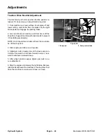
4. Loosen bedknife to reel adjustment so their is no bed-
knife to reel contact on all cutting units
5. Set HOC Selector Knob, located under the instru-
ment panel, to position A (full speed). Make sure Back-
lap switch is OFF.
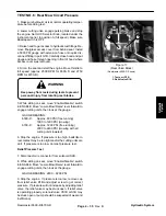
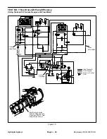
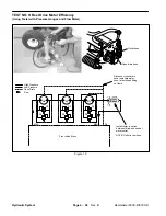
6. Install tester in series between outlet fitting and hose
of last motor in series. Make sure the tester flow control
valve is OPEN.
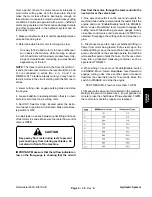
Keep away from reels during tests to prevent
personal injury from rotating reel blades. Do
not stand in front of the machine.
IMPORTANT: Make sure that the oil flow indicator ar-
row on the flow gauge is showing that the oil will
flow from the motor, through the tester and into the
next motor or the valve block.
7. One person should sit on the seat and operate the
machine while another person reads the tester. Start the
engine and move “Enable/Disable” switch to ENABLE.
Move “Lower–Mow/Raise” lever forward to engage the
cutting units. While watching pressure gauges, slowly
close flow control valve until a pressure of 2000 PSI is
obtained. Disengage the cutting units and stop the en-
gine.
8. Disconnect case drain hose (at bulkhead fitting on
frame) from motor being tested. Put a steel cap on the
bulkhead fitting. Leave the case drain hose open. One
person should sit on the seat and operate the machine
while another person holds the hose. Put the case drain
hose into a graduated measuring container, such as
special tool TOR4077.
9. While sitting on seat, move “Enable/Disable” switch
to ENABLE. Move “Lower–Mow/Raise” lever forward to
engage cutting units. Have another person measure
flow from the case drain line for 15 seconds. Move the
switch to DISABLE and stop the engine.
TEST RESULTS: Flow not more than .7 GPM.
10. Measure the amount of oil collected in the container.
Multiply the amount collected by 4 (to get gallons per
minute) or use the chart below. If flow exceeded .7 GPM,
the reel motor should be repaired or replaced.
Hydraulic System
Summary of Contents for REELMASTER 6500 D
Page 2: ...Reelmaster 6500 D 6700 D ...
Page 4: ...Reelmaster 6500 D 6700 D ...
Page 10: ...Reelmaster 6500 D 6700 D Page 1 6 Safety ...
Page 12: ...Reelmaster 6500 D 6700 D Page 2 2 Product Records and Manuals Equivalents and Conversions ...
Page 20: ...Rev C Reelmaster 6500 D 6700 D Page 2 10 Product Records and Manuals ...
Page 24: ...Rev C Reelmaster 6500 D 6700 D Page 2 14 Product Records and Manuals ...
Page 86: ...Engine Page 3 62 Reelmaster 6500 D 6700 D ...
Page 202: ...Reelmaster 6500 D 6700 D Page 5 8 2 Electrical System Rev C This page is intentionally blank ...
Page 226: ...Reelmaster 6500 D 6700 D Page 5 26 6 Electrical System Rev B This page is blank ...
Page 276: ...Reelmaster 6500 D 6700 D Page 6 22 Axles Planetaries and Brakes ...
Page 300: ...Reelmaster 6500 D 6700 D Page 7 24 Cutting Units Rev B Model 03853 Model 03854 Model 03855 ...

