background image

Reelmaster 6500–D/6700–D

Page 4 – 49

Hydraulic System

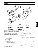
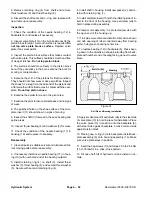
Wheel Motor

T–2117

1

2

3

4

5

6

7

8

9

10

16

17

18

19

11

12

13

14

15

4

5

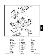
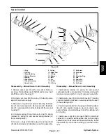
Figure 28

1. Retaining Ring

8. HH Screw

15. Valve Plate

2. Shaft Seal

9. Backplate Assembly

16. Rotating Kit

3. Washer

10. O–Ring

17. Camplate Insert

4. Retaining Ring

11. Speed Pickup Sensor

18. Housing

5. Thrust Race

12. Dowel Pin

19. Needle Bearing

6. Thrust Bearing

13. Dowel Pin

7. Splined Drive Shaft

14. Needle Bearing

Cleanliness is extremely important when repairing
these motors. Work in a clean area. Before disconnect-
ing the lines, clean port area of motor. Disconnect hy-
draulic lines, removing motor assembly from vehicle
and plug ports. Thoroughly clean the outside of the mo-
tor. After cleaning, remove port plugs and drain oil.

Tools Required for Disassembly and Reassembly

1/2 in. Socket
Ratchet Wrench
Torque Wrench, 68 Nm [50 Ibs. ft.]
Soft Face Hammer
Internal Retaining Ring Pliers

(Straight 2.3mm[.090 in.] Tip)

External Retaining Ring Pliers

(Straight 1.8mm[.070 in.] Tip)

Seal Driver or Similar Tool
Petroleum Jelly (Such as Vaseline)

Disassembly

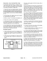
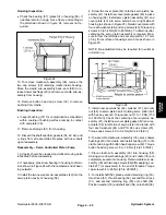
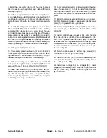
1. Clamp the drive shaft end of the piston motor in a pro-
tected jaw vise with the cap screws up. Remove the six
cap screws (8) from the motor assembly.

2. Use a mallet and tap the backplate (9) to loosen and
remove from housing.

3. Remove valve plate (15) and O–ring (10) from back-
plate. It is not necessary to remove roll pins in backplate.

4. Remove motor from vise and remove rotating assem-
bly (16) from motor housing.

5. Remove the camplate insert (17) from housing (18).
Use caution not to mar the finish that makes contact with
pistons.

6. Remove retaining ring (1) from housing. Press shaft
(7) from housing (18) and remove shaft seal (2), and
washer (3).

Hydraulic System

Summary of Contents for REELMASTER 6500 D

Page 1: ...ng complete Model and Serial Num ber to The Toro Company 8111 Lyndale Avenue South Minneapolis MN 55420 The Toro Company reserves the right to change product specifications or this publication without notice This safety symbol means DANGER WARN ING or CAUTION PERSONAL SAFETY INSTRUCTION When you see this symbol carefully read the instructions that follow Failure to obey the instructions may result...

Page 2: ...Reelmaster 6500 D 6700 D ...

Page 3: ...leshooting 4 20 Testing 4 29 Adjustments 4 40 Repairs 4 42 Chapter 5 Electrical System Wiring Schematics S N 50001 59999 5 2 Wiring Schematics S N 60001 UP 5 8 Main Wire Harness Connector Diagram 5 18 Special Tools 5 19 Troubleshooting 5 21 Electrical System Quick Checks 5 33 Component Identification and Testing 5 35 Repairs 5 49 Chapter 6 Axles Planetaries and Brakes Specifications 6 2 Special To...

Page 4: ...Reelmaster 6500 D 6700 D ...

Page 5: ... manual is avail able by sending the complete model and serial number to The Toro Company 8111 Lyndale Avenue South Minneapolis Minnesota 55420 1196 Use the Model and Serial Number when referring to your machine If you have questions about this Service Manual please contact The Toro Company Commercial Service Department 8111 Lyndale Avenue South Minneapolis Minnesota 55420 2 Never allow children t...

Page 6: ... good ar tificial light B Drive slowly C Watch for holes or other hidden hazards D Look behind machine before backing up E Do not drive close to a sand trap ditch creek or other hazard F Reduce speed when making sharp turns and turning on a hillside G Avoid sudden stops and starts 15 Traverse slopes carefully Do not start or stop sud denly when traveling uphill or downhill 16 Operator must be skil...

Page 7: ...nnecting or performing any work on the hydraulic system all pressure in system must be re lieved by stopping engine and lowering cutting units to the ground 28 If major repairs are ever needed or assistance is de sired contact an Authorized Toro Distributor 29 To reduce potential fire hazard keep engine area free of excessive grease grass leaves and dirt Clean protective screen on front of engine ...

Page 8: ...ER Part No 93 6686 Hydraulic Oil Only ON LEFT FENDER Part No 93 6680 Diesel Fuel Only IN TOOL BOX Part No 93 3728 Quick Reference Aid UNDER SEAT PLATE Part No 98 8110 Selecting Clip Rate Solenoid Wire Identification INSIDE CONTROL BOX Part No 94 6349 Fuse Locations UNDER FLOOR PLATE Part No 93 6693 WARNING Moving Parts under floor plate INSIDE CONTROL BOX Part No 93 1268 Operating Instructions H O...

Page 9: ...265 WARNING Hot Surface Do Not Touch ON CONSOLES Part No 93 6689 WARNING No Riders ON ROLL BAR ROOF Part No 93 8050 Model 03804 only WARNING Fasten Seat Belt ON ROLL BAR Part No 92 7540 Model 03804 only ROPS Serial Tag ON BACKLAP BRACKET Part No 93 1264 WARNING Read Backlap Operating Safety Instructions ON UNDERSIDE OF SEAT PLATE Part No 98 8108 Solenoid Wire Identification ON UNDERSIDE OF SEAT PL...

Page 10: ...Reelmaster 6500 D 6700 D Page 1 6 Safety ...

Page 11: ...gs and Torque Values U S 4 Capscrew Markings and Torque Values Metric 5 Other Torque Specifications 6 Conversion Factors 6 QUICK REFERENCE MAINTENANCE AID 7 Bearing and Bushing Lubrication 8 OPERATION AND SERVICE HISTORY REPORT 11 Product Records Record information about your machine on the OPERA TION AND SERVICE HISTORY REPORT form Use this information when referring to your machine Insert Operat...

Page 12: ...Reelmaster 6500 D 6700 D Page 2 2 Product Records and Manuals Equivalents and Conversions ...

Page 13: ...n the fastener presence of a prevailing torque feature hard ness of the surface underneath the fastener s head or similar condition which affects the installation As noted in the following tables torque values should be reduced by 25 for lubricated fasteners to achieve the similar stress as a dry fastener Torque values may also have to be reduced when the fastener is threaded into aluminum or bras...

Page 14: ... 2 16 2 22 3 30 3 41 4 43 4 58 5 3 8 24 UNF 17 2 18 2 24 3 35 3 47 4 50 4 68 5 7 16 14 UNC 27 3 27 3 37 4 50 5 68 7 70 7 95 9 7 16 20 UNF 29 3 29 3 39 4 55 5 75 7 77 7 104 9 1 2 13 UNC 30 3 48 7 65 9 75 8 102 11 105 10 142 14 1 2 20 UNF 32 3 53 7 72 9 85 8 115 11 120 10 163 14 5 8 11 UNC 65 10 88 12 119 16 150 15 203 20 210 20 285 27 5 8 18 UNF 75 10 95 15 129 20 170 15 230 20 240 20 325 27 3 4 10...

Page 15: ...ft lb 90 10 N m 92 9 ft lb 125 12 N m M16 X 2 0 166 15 ft lb 225 20 N m 229 22 ft lb 310 30 N m M20 X 2 5 325 33 ft lb 440 45 N m 450 37 ft lb 610 50 N m Note Reduce torque values listed in the table above by 25 for lubricated fasteners Lubricated fasteners are defined as threads coated with a lubricant such as oil graphite or thread sealant such as Loctite Note Torque values may have to be reduce...

Page 16: ...100 in lb Wheel Bolts and Lug Nuts Thread Size Recommended Torque 7 16 20 UNF Grade 5 65 10 ft lb 88 14 N m 1 2 20 UNF Grade 5 80 10 ft lb 108 14 N m M12 X 1 25 Class 8 8 80 10 ft lb 108 14 N m M12 X 1 5 Class 8 8 80 10 ft lb 108 14 N m For steel wheels and non lubricated fasteners Thread Cutting Screws Zinc Plated Steel Thread Size Threads per Inch Baseline Torq e Size Type A Type B Baseline Torq...

Page 17: ...Rev C Reelmaster 6500 D 6700 D Page 2 7 Product Records and Manuals Product Records and Manuals ...

Page 18: ...ine is operated under normal condi tions lubricate all bearings and bushings after every 50 hours of operation or immediately after every washing 1 The grease fitting locations and quantities are Cut ting unit carrier frame and pivot 2 ea Fig 1 Rear axle tie rod 2 Steering cylinder ball joints 2 Fig 2 Front lift cylinders 3 Fig 4 and 8 Rear lift cylinder pivot 2 Fig 5 Lift arm pivot 3 Fig 6 Rear a...

Page 19: ...Rev C Reelmaster 6500 D 6700 D Page 2 9 Product Records and Manuals Figure 7 Figure 8 Figure 9 Product Records and Manuals ...

Page 20: ...Rev C Reelmaster 6500 D 6700 D Page 2 10 Product Records and Manuals ...

Page 21: ..._________________________ Drive Axle s Numbers _____________________________ Date Purchased _____________________________ Warranty Expires____________ Purchased From _____________________________ _____________________________ _____________________________ Contacts Parts _____________________________ Phone____________________ Service _____________________________ Phone____________________ Sales ___...

Page 22: ...and Clean Fuel Tank Change Hydraulic Oil Change Hydraulic Oil Filter Change Front Planetary Gear Lube Pack 2WD Rear Axle Bearings Change Rear Axle Oil Level 4wd Check Rear Wheel Toe In Initial break in at 10 hours Initial break in at 50 hours Initial break in at 200 hours If indicator shows red Replace Moving Hoses Replace Safety Switches Cooling System Flush Replace Fluid Maintenance Procedure Ev...

Page 23: ...n Indicator n Radiator Screen for Debris n Unusual Engine Noises1 n Unusual Operating Noises n Hydraulic System Oil Level n Hydraulic Filter Indicator2 n Hydraulic Hoses for Damage n Fluid Leaks n Tire Pressure n Instrument Operation n Reel to Bedknife Adjustment n Height of Cut Adjustment Lubricate All Grease Fittings3 Touch up Damaged Paint 1 Check glow plug and injector nozzles if hard starting...

Page 24: ...Rev C Reelmaster 6500 D 6700 D Page 2 14 Product Records and Manuals ...

Page 25: ...mp Fuel Delivery Test 31 Thermostat Test 32 FUEL SYSTEM SERVICE 33 Priming the Fuel System 33 Injection Pump Removal 33 Injection Pump Repair 33 Injector Service 34 TIMING BELT REPLACEMENT 36 Timing Belt Removal 36 Timing Belt Installation 38 INJECTION PUMP TIMING 40 Timing of Injection Pump 40 PREPARATION FOR ENGINE REPAIR 42 Cylinder and Cylinder Block 42 ENGINE REMOVAL AND INSTALLATION 43 ENGIN...

Page 26: ...d the specialized nature of some repairs may dictate that the work be done at a qualified diesel engine repair facility Service and repair parts for the Peugeot engine used in the Reelmaster 6500 D and 6700 D are supplied through TORO Distributors Repair parts may be or dered by TORO Part Number If no parts list is available be sure to provide your dealer or distributor with the TORO Model Number ...

Page 27: ...ting wrist pin ________________________________________________________________________________________________________________________________________________________ Lubrication Full pressure feed by gear type pump ________________________________________________________________________________________________________________________________________________________ Oil Filter Full flow cartridge...

Page 28: ...e following operations must be done 1 Valve seat machining to re establish correct re cess see Valve Recess in this section 2 Replacement of swirl chambers by repair dimen sion and correction of their protrusion see Swirl Chambers in this section 3 Fitting of 0 4 mm thick compensation washers under the valve springs to match cylinder head machining Cylinder heads manufactured with oversize camshaf...

Page 29: ...ange engines and can be obtained on special order Figure 4 Valves Intake Exhaust Min Length l 112 2 øa 0 0 015 8 005 7 985 øb 0 1 38 5 33 a 90 90 Intake Faces x and y can machined a maximum of 0 2 mm Exhaust No machining is permissible Figure 5 Valve Recess Intake Exhaust c 0 5 to 1 05 0 9 to 1 45 Figure 6 Units mm Units mm Engine Reelmaster 6500 D 6700 D Page 3 5 Engine ...

Page 30: ... j øk Tolerance 0 0 011 0 032 0 0 25 0 50 0 0 2 Production 14 02 14 13 13 981 14 051 Repair 1 14 29 14 211 52 00 36 50 8 02 Repair 2 14 59 14 511 øk is obtained by machining after fitting in the cylinder head Figure 8 Units mm Units mm Engine Page 3 6 Reelmaster 6500 D 6700 D ...

Page 31: ...7 34 3 6 25 8 35 Repair 2 34 637 34 5 6 25 8 35 After fitting valve seats into the cylinder head machine them according to drawings Fig 9 Figure 9 Swirl Chambers øe øf g h Tolerance 0 099 0 060 0 039 0 0 020 0 025 0 02 0 04 Production 32 05 32 25 32 32 2 4 4 1 3 9 4 Repair 1 32 45 32 4 4 2 4 1 Repair 2 32 65 32 6 4 3 4 2 The protrusion j must be between 0 and 0 03 mm Dimension j is obtained by mac...

Page 32: ... 96 Repair 1 R1 83 20 83 13 Repair 2 R2 83 50 83 43 Repair 3 R3 83 80 83 73 NOTE The piston øb must be measured at dimension c C 25 00 NOTE The repair dimension x is stamped on the cylinder block and pistons Figure 11 Piston Pin ø external 24 994 to 25 ø internal 13 8 to 14 1 Units mm Units mm Engine Page 3 8 Reelmaster 6500 D 6700 D ...

Page 33: ... bearing shells can be identified by white paint 1 on the edge of the shell End Float No 2 Journal Half Shell Thickness e f Tolerance 0 05 0 0 025 Production 26 60 2 305 Repair 1 26 80 2 405 Repair 2 26 90 2 455 Repair 3 27 00 2 505 Oil Seal Contact Surface øg Tolerance 0 0 087 Production 90 00 Repair 1 89 80 Figure 13 Units mm Units mm Units mm Engine Reelmaster 6500 D 6700 D Page 3 9 Engine ...

Page 34: ..._____________________________________________________________________________________________ Injector into Cylinder Head 90 9 66 ________________________________________________________________________________________________________________________________________________________ Main bearing caps 70 7 52 ___________________________________________________________________________________________...

Page 35: ...TOR80504A2 Indicator Holder Fig 30 TOR80110GY Extension Rod Adapter Fig 24 TOR70153A1 Main Seal Installer Fig 18 TOR70153A2 Main Seal Installer Shims Fig 19 TOR70153C Rear Main Seal Installer Fig 20 TOR70153D Front Cover Seal Installer Fig 21 TOR4035 Tune Up Set This tool kit includes tools required for doing timing belt replacement injection pump timing injector removal and camshaft seal replacem...

Page 36: ...er head gasket selection adjusting the timing of the injection pump and for checking the crankshaft and float TOR4024T Valve Spring Compressor This tool is used to compress valves for removal TOR70153A1 Main Seal Installer Used to install the two side seals to the no 1 main bearing cap TOR70153A2 Shim Set Used with main seal installer TOR70153A1 Figure 16 Figure 17 Figure 18 Figure 19 Engine Page ...

Page 37: ...er Used with a small hammer to install new front crankshaft seal TOR70153N Flywheel T D C Locator Pin Used to set injection pump timing TOR80110DZ 2mm Shim Cut Off Gauge With Cut Off Shim Used to gage and gut off new side seals to 2mm height Figure 20 Figure 21 Figure 22 Figure 23 Engine Reelmaster 6500 D 6700 D Page 3 13 Engine ...

Page 38: ...usion of swirl chambers valve recess and measurement for cylinder head gasket selection TOR80117AM Timing Tool Kit For Roto Diesel DPC Pump Used with dial indicator to adjust timing of injection pump TOR80117EZ Crankshaft Rotating Wrench Used with a 1 2 drive ratchet wrench to turn the crank shaft Figure 24 Figure 25 Figure 26 Figure 27 Engine Page 3 14 Reelmaster 6500 D 6700 D ...

Page 39: ... 80110GY and TOR 80504A2 to check crankshaft end float TOR 80504A2 Indicator Holder Used with TOR80110GY and TOR 80504A1 to check crankshaft end float TOR976697 Camshaft Seal Installer Used to install camshaft seal Figure 28 Figure 29 Figure 30 Figure 31 Engine Reelmaster 6500 D 6700 D Page 3 15 Engine ...

Page 40: ...ylinder head qty 2 required TOR70153H Injector Pump Gear Puller Loosen the nut on the injector pump gear then use this tool to loosen the pulley from the tapered shaft on the injector pump Figure 32 Figure 33 TOR70153H Units mm Engine Page 3 16 Reelmaster 6500 D 6700 D ...

Page 41: ...r Throttle Cable Adjustments The throttle control lever at the operator s station must not touch the end of the slot during full range of motion from idle SLOW to full engine RPM FAST Adjust throttle cable at injection pump so throttle lever on injection pump operates at full range of motion without throttle control lever at operator s station touch ing end of slot at either FAST or SLOW position ...

Page 42: ...uit defective Energizing circuit defective Brushes worn or seized Rotor winding defective Stator winding defective Regulator defective Rotor partially short circuited Stator partially short circuited Rectifier diode defective Rectifier diode short circuited Battery voltage too high In line diode defective Regulator defective Poor connections Alternator noisy Rectifier diode short circuited Belt wo...

Page 43: ...rain water and flush fuel feed system 1 Replace gasket at each repair Tighten injector nut 1 Leakage collector fills too quickly Leak between upper bearing face of nozzle and bearing face of injector body Foreign matter between bearing faces Unevenness Clean Replace injector Blue needle point Incorrect injection pump timing Replace injector and adjust pump timing again End of injector body corrode...

Page 44: ... discharged valve Blocked pump governor Have pump repaired Have pump repaired Have pump repaired Engine will not accelerate Defective fuel supply Seized pump plunger Broken pump plunger spring Hard discharge valve Seized feed pump Accelerator linkage defective Check filter cartridge and pipes Have pump repaired Have pump repaired Have pump repaired Drain water from tank pipes and filter have pump ...

Page 45: ...pipes Check clean and adjust injectors Have pump repaired Have pump repaired Noisy engine Incorrect pump timing Blocked automatic advance Automatic advance to far advanced Correct timing Have pump repaired Have pump repaired Engine stalls at idling Air getting into fuel system Idling stop out of adjustment Jammed discharge rate Check gaskets and pipes Adjust idling stop Have pump repaired Vibratin...

Page 46: ...ion pipe restriction due to excessive tightening of unions Defective injection pump Irregular idling Defective injection pump Air getting into fuel system Idling stop out of adjustment Leaky injection pipe unions Speed fall Off Clogged fuel filter Defective injection pump Engine speed rises to maximum Defective injection pump Throttle cable jammed Engine Page 3 22 Reelmaster 6500 D 6700 D ...

Page 47: ... collector clogged Lifters out of adjustment Foreign matter in a cylinder Seized injector Injection pump timing Sheared glow plug Timing out of adjustment Whistling blowing Leaking cylinder head gasket Leaky glow plug Valve seats Leaky injector Engine Reelmaster 6500 D 6700 D Page 3 23 Engine ...

Page 48: ... glow red hot Faulty glow plug Faulty glow plug relay Damaged wiring or connector All four glow plugs burnt out ends melted injection pump timing out of adjustment engine overheating See Chapter 5 Electrical System Engine Page 3 24 Reelmaster 6500 D 6700 D ...

Page 49: ...e restricted Inlet chambers clogged Not enough advance Grey Defective injector Injection pump timing Air intake restricted Not enough advance Blue Grey Defective injector Injection pump timing Too much oil Blue Too much oil Wear White Injection pump timing Cylinder head gasket Cold engine Engine Reelmaster 6500 D 6700 D Page 3 25 Engine ...

Page 50: ...inder head gasket Engine will not start and does not emit any smoke Frozen fuel Injection pump does not work Leaking injection pipe unions Injection valve blocked No preheating Empty fuel tank Feed pipe obstructed Air getting in pipes Tank vent plugged Injection pump needs re priming Shutdown control jammed in stop position Starter does not crank or cranks slowly Battery discharged Oil too thick E...

Page 51: ...e glow plug 3 Inspect the glow plug for signs of a burnt glow plug end tube NOTE If the metal of the glow plug end is melted it is a sign of cylinder overheating 4 Connect the positive battery terminal to the glow plug terminal and the negative battery terminal to the plug body Fig 34 If the glow plug glows red hot in 9 to 12 seconds the glow plug is operating correctly DO NOT leave on more than 2...

Page 52: ...pressure compression gauge to the adapter 4 Disconnect the fuel stop solenoid electrical connector or hold the fuel stop lever in the stop position to prevent fuel delivery during the compression test This will pre vent wash down of the cylinders and inaccurate read ings 5 Crank the engine with the starter motor until you get a stable gauge reading 6 If the pressure is less than 20 bar 290 psi it ...

Page 53: ...nto the combustion chamber at a precise point in the compres sion stroke The point at which this fuel injection occurs is determined by the injection timing If the nozzle is defective damaged or adjusted incorrectly starting fail ures low power output or engine knocking can occur 1 Securely fasten the nozzle to the adapter 2 Pump the handle several times to purge air from the nozzle mechanism 3 Al...

Page 54: ...While pressure is being applied watch for an accu mulation of fuel at the tip of the nozzle Fig 35 A small amount of fuel may be present due to a previous chat tering test this would be normal If the fuel accumulates and drips down during the test about ten seconds the nozzle assembly is defective and must be replaced Spray Test For proper combustion the nozzle must effectively at omize the inject...

Page 55: ...o the tip of the nozzle is pointed away from the engine Tighten the fitting securely D Put the throttle control in the FAST position Turn the ignition key to the START position to crank the engine Observe the nozzle The injection pump forces fuel from the noz zle under extremely high pressure Always point the nozzle tip away from yourself and any other personnel Contact with the fuel stream even t...

Page 56: ...ested 1 Remove the thermostat 2 Put the thermostat in a container of water with a thermometer and heat the water Starts to open at 81o C 178o F 7 mm 0 28 in full open at 88o C 190o F 3 If the thermostat fails to open only partially opens or sticks it should be replaced Figure 37 Engine Page 3 32 Reelmaster 6500 D 6700 D ...

Page 57: ...nd pump priming plunger until a steady stream of fuel comes out of fitting When fuel stops foaming tighten the fitting during the down stroke of the priming plunger Wipe up any spilled fuel NOTE The high pressure fuel system is self bleeding It is not necessary to open the high pressure lines Figure 38 1 Primer plunger 2 Bleed screw Figure 39 1 Injection pump fitting Injection Pump Removal See Inj...

Page 58: ...eaning 1 Secure the injector body in a V type injector holder 2 Remove the injector holder nut 3 Remove the injector spacer push rod pressure setting spring adjusting shims and body 4 Dip all parts in clean diesel fuel 5 Clean nozzle and needle in clean diesel fuel 6 De carbon injector nozzle using a wooden spatula Never use metallic objects emery cloth or rags Do not attempt to grind the needle o...

Page 59: ...ne new washers must be installed Fire ring washer is installed with convex surface up 1 Install new fire ring washers Fig 58 Item 21 convex surface facing up 2 Install new copper washers Fig 58 Item 20 3 Install the injectors and tighten to a torque of 90 Nm 66 ft lb 1 Install new flame arrestor steel washer and copper gasket 2 Install injector in cylinder head 3 Install injection pipe unions on p...

Page 60: ...elt covers Item 2 3 and 4 in the numbered order 4 Re install the crankshaft bolt Fig 44 Item 1 and the washer 5 Lock the camshaft gear Item 6 in position by install ing an M8 x 125 x 40 bolt Tighten finger tight 6 Lock the injection pump gear Item 7 in position with two M8 x 125 x 35 bolts Tighten finger tight IMPORTANT To prevent damage to the face of the injector pump housing and future timing p...

Page 61: ...m 9 securing the roller tensioner bracket Item 10 8 Rotate the roller tensioner bracket square Item A to compress the spring Item 11 9 Re tighten the bolt Item 9 10 Remove the timing belt A Figure 45 Engine Reelmaster 6500 D 6700 D Page 3 37 Engine ...

Page 62: ...ction pump gear Item B Camshaft gear Item C Tensioner roller Item 17 Coolant pump gear Item 10 2 Loosen the bolt Fig 47 Item 18 and nut Item 19 to release the tensioner roller DO NOT use Item A to set tension Tension on belt is only to be set by the spring Fig 46 Item 15 when tensioner plate is free to rotate 3 Re tighten the bolt Item 18 then the nut Item 19 when the belt is tensioned A Figure 47...

Page 63: ... Item 18 then the nut Item 19 to a torque of 17 5 Nm 13 ft lb 9 Remove the three gear locking bolts 10 Install the covers Fig 49 Item 2 3 and 4 cover clips and cover attachment nut Item 5 11 Install the pulley A Clean with a brush and de grease the threads of the bolt Fig 50 Item 1 the bearing faces of the washer Item 2 and the head of the bolt Item 1 B Coat the threads of the bolt Item 1 with thr...

Page 64: ... Item 6 in position with a M8 x 125 x 40 bolt Tighten finger tight B Lock the injection pump gear Item 7 in position with two M8 x 125 x 35 bolts Tighten finger tight NOTE If the locking bolts cannot be installed be cause the holes in the gears and engine block do not align remove the TDC Lock Pin tool and rotate the engine clockwise one revolution Install the TDC Lock Pin then install the bolts a...

Page 65: ...o to far and the reading is passed stop Again rotate the pump away from the engine then rotate the pump toward the engine in one smooth motion 12 After obtaining the correct reading be careful to keep the pump in position and tighten the pump bolts 13 Remove the TDC Lock Pin tool TOR 70153 N 14 Turn the crankshaft 1 4 to 1 3 turn in the opposite direction of running counterclockwise as viewed from...

Page 66: ...verhaul Before removing any parts disassembly or overhaul of the Peugeot engine it is very important to understand the nature and probable cause of the problem that made an overhaul necessary When the engine trouble is caused by worn cylinders rings or valves one or more of the following symptoms will occur 1 Low engine power and a decrease in compression pressure 2 Increased fuel consumption 3 In...

Page 67: ...oolant to drain into a pan 6 Drain coolant from engine block DO NOT open radiator cap or drain coolant if engine or radiator is hot Pressurized hot coolant can escape and cause burns 7 Disconnect upper and lower radiator hoses from engine and radiator 8 Remove fuel hose from injector pump Plug end of fuel line to prevent fuel leakage Disconnect injector return hose 9 Disconnect PCV hose from engin...

Page 68: ...ne out of chassis Remove engine from chassis Be careful when remov ing engine to prevent damage to engine radiator or other parts Mount engine in an engine rebuilding stand 17 Remove muffler brackets coolant expansion tank and accessories from engine as necessary Drain oil from engine and remove engine oil filter Installing the Engine 1 To install the engine perform steps 2 17 of Removing the Engi...

Page 69: ... exhaust manifold and inlet manifold 5 Remove the coolant manifold 6 Remove the alternator and belt 7 Remove the oil filter Fig 57 Item 10 8 Remove the injector pipes Item 12 9 Remove the glow plug leads 10 Remove the crankcase breather pipes oil filter filter pipe assembly Item 13 11 Remove the oil pressure switch Item 14 Figure 57 Engine Reelmaster 6500 D 6700 D Page 3 45 Engine ...

Page 70: ... Fig 58a Item 5 3 Remove the injection pump Fig 58b Item 19 4 Remove bracket Item 20 NOTE If the pump needs to be inspected or repaired it is recommended that is be done by an authorized CAV Lucas ROTO DIESEL service dealer especially during the warranty period Repairs by non authorized dealers WILL void the pump warranty IMPORTANT Clean the injection pump and the area around the injection pump be...

Page 71: ... Pump Removal 1 Remove the oil pan and gasket IMPORTANT Use solvent and a wood or plastic scraper to remove the silicone gasket material Be careful not to damage the sealing face of the block 2 Remove the bolts Fig 60 Item 1 2 and 3 3 Remove the seal carrier plate Item 4 IMPORTANT The bolt Item 1 is a special bolt that centers the pump in the correct location 4 Remove the pump Fig 61 Item 5 drive ...

Page 72: ...2 cap 5 Remove the oil seal Fig 63 Item 10 6 Remove the end float washers Item 11 7 Remove the crankshaft 8 Remove the main bearing shells 9 Remove the piston connecting rod assemblies mark ing each piston and connecting rod for re installation in the same location NOTE Connecting rods and end caps are not num bered Once they are removed there is no way of knowing the correct location for installa...

Page 73: ...to remove the swirl chambers from the injector orifices if necessary NOTE Swirl chambers do not need to be removed unless cylinder head is to be machined or replaced 5 Clean the cylinder head Use a wooden scraper and gasket stripping solvent to clean the gasket face DO NOT use a metal scraper 6 Check the gasket face for bow flatness Check corner to corner and side to side Fig 67 Maximum bow 0 7 mm...

Page 74: ...n 12 Install the shims as removed in step 2 If replacing cylinder head or if cylinder head has been machined install a basic shim Fig 69 Item 6 2 425 mm thick to each valve stem and check that each shim is higher than the spring cup Item c If a shim is not higher than the cup grind the top of the cup Item c 13 Re install the tappets 14 Oil the camshaft bearings 15 Install the camshaft with the DIS...

Page 75: ...main bearing shell thickness 3 Install the crankshaft 4 Install the no 3 4 and 5 main bearing caps 5 Install the two end float half washers Fig 72 Item 1 with the anti friction faces towards the crankshaft 6 Install the no 2 main bearing cap Fig 73 Item 2 with its two end float half washers with the anti friction faces towards the crankshaft Figure 71 Figure 72 Figure 73 Engine Reelmaster 6500 D 6...

Page 76: ... 1 main bearing cap 10 Using a bolt and washer Item 5 attach tool 80153 fitted with shims A2 to no 1 main bearing cap Item 4 11 Adjust the height x of the shims x 0 5 mm above flat on side of rear main cap 12 Oil the shims and the housing IMPORTANT To avoid stretching the side seals fit the cap as follows A Engage it in its housing at 45 B Straighten it C Lower it slowly D Tighten the two bearing ...

Page 77: ...he connecting rods and pistons with the bearing shell tab recess Fig 77 Item a on the same side as the piston crown recess Item b 2 Use a piston rings pliers to install the piston rings NOTE The marked face of the tapered ring must be towards the combustion chamber 1 scraper ring 2 tapered ring 3 domed chrome ring Space the ring gaps at 120 in relation to the scraper ring gap Item c Figure 77 TOR ...

Page 78: ...r choice of bearing shell thickness see Crank case in Identification and Specifications section Figure 78 Oil Seal Installation 1 Put a new oil seal on tool TOR 70153 C Figure 79 Oil Pump Installation 1 Install the key Fig 80 Item 6 2 Install the pump Item 7 drive chain and sprocket Item 8 assembly Figure 80 TOR 70153C Engine Page 3 54 Reelmaster 6500 D 6700 D 2 Install seal with lip toward the in...

Page 79: ...tern shown in Figure 81a Wait 10 minutes before installing the oil pan to allow partial hardening of the gasket material 10 Install the oil pan Item 5 11 Install the bolts Item b NOTE The two shorter bolts are installed into the main bearing cap 12 Tighten the bolts Item b to a torque of 20 Nm 15 ft lb 13 Wait a minimum of 1 hour for the oil pan gasket to harden before filling with oil Figure 81 F...

Page 80: ...0 75 to 0 79 4 notches 0 79 to 0 83 5 notches Figure 82 Cylinder Head Installation 1 Turn the crankshaft to put the pistons at mid stroke with damper pulley key Fig 83 Item 6 at the 9 o clock position 2 Clean the tapped holes in the cylinder block 12 x 150 thread 3 Install the centralizing dowel Item 7 4 Install a new head gasket dry 5 Install the cylinder head 6 Carefully clean the threads of the...

Page 81: ...alled 5 times before replacing with new bolts Figure 84 Valve Clearance Adjustment NOTE If all valve parts are re installed in their original location it should not be necessary to adjust valve clearance unless the head has been machined or valves ground 1 Install the camshaft gear Fig 85 Item 1 2 Check the valve clearance Running Clearance Inlet 0 15 Exhaust 0 30 Tolerance 0 04 Set on the rock In...

Page 82: ...Item 5 8 Determine the shim thickness to be fitted for each valve Example No 1 Intake valve Specified clearance 0 15 Clearance measured 0 25 Difference 0 10 Shim installed 2 425 Shim to be installed 2 50 Clearance obtained 0 175 Basic shim 9 Install the shims as determined in step 8 10 Install the tappets Figure 86 Units mm Engine Page 3 58 Reelmaster 6500 D 6700 D ...

Page 83: ...rking at the timing gear end 14 Install the camshaft bearing caps Item 2 as shown by cast in markings 15 Progressively tighten the bearing caps to 17 5 Nm 13 ft lb 16 Install a new oil seal on tool TOR 976697 on the side where the inner flange is the farthest away Fig 88 17 Use a camshaft gear or pulley bolt to install the two camshaft oil seals Figure 87 Figure 88 TOR 976697 Engine Reelmaster 650...

Page 84: ...7 ft lb 7 Install the pre heat plug wires 8 Install the breather pipe assembly with oil filler pipes and filler orifice Fig 90 Item 13 9 Install the injector pipes Item 12 10 Install the oil pressure switch Item 14 and tighten to a torque of 27 5 Nm 20 ft lb 11 Install a new oil filter Item 10 See Break in Engine After Overhaul 12 Install the alternator and alternator belt 13 Install the water inl...

Page 85: ...fter Overhaul After disassembling or overhauling the engine install the a new oil filter Replace this filter with a new filter after the first 20 to 50 hours of operation Engine Reelmaster 6500 D 6700 D Page 3 61 Engine ...

Page 86: ...Engine Page 3 62 Reelmaster 6500 D 6700 D ...

Page 87: ...t No 2 Traction Circuit System Pressure 31 Test No 3 Steering Circuit Pressure 32 Test No 4 Lift Circuit Pressure 33 Test No 5 Front Mow Circuit Pressure 34 Test No 6 Rear Mow Circuit Pressure 35 Test No 7 Reel Drive Lift Pump Efficiency 36 Test No 8 Reel Drive Motor Cross over Relief Pressure 37 1 Test No 9 Reel Drive Motor Efficiency 38 ADJUSTMENTS 40 Traction Drive Neutral Adjustment 40 Cutting...

Page 88: ...idge logic elec hyd solenoid actuated Front Rear Reel Circuit Relief Pressure 3000 3200 PSI Lift Relief Pressure 2600 2900 PSI Reel Motor Gear motor Cross over Relief Pressure 1400 1600 PSI Hydraulic Filter Spin on cartridge type 50 PSI by pass Hydraulic Fluid Group 1 for ambient temp consistently below 100F ISO type 46 68 anti wear hydraulic fluid Mobil 424 or equiv Group 2 Biodegradable ISO VG 3...

Page 89: ... to search for leaks Hydraulic fluid escaping under pressure can have sufficient force to penetrate the skin and do serious damage If fluid is injected into the skin it must be surgically removed within a few hours by a doctor familiar with this type of in jury or gangrene may result Hydraulic Fitting Installation O Ring Face Seal Fig 2 3 1 Make sure both threads and sealing surfaces are free of b...

Page 90: ...sealing surfaces are free of burrs nicks scratches or any foreign material 2 Always replace the O ring seal when this type of fit ting shows signs of leakage 3 Lubricate the O ring with a light coating of oil 4 Turn back the jam nut as far as possible Make sure the back up washer is not loose and is pushed up as far as possible Step 1 5 Install the fitting into the port and tighten finger tight un...

Page 91: ... pass valve must be open whenever the machine is pushed or towed 1 By pass valve is located on top of variable displace ment pump Fig 7 Rotate the valve 90_ in either direc tion to open and allow oil to by pass internally Because fluid is by passed the machine can be moved slowly without damaging the transmission 2 Close by pass valve before starting the engine How ever do not exceed 5 8 ft lb 7 1...

Page 92: ... R3 040 040 060 R1A G1A R2A G1B C3B C3 C2 C2B M8 M9 R5 R6 R6 P4 R7 R4 V1 R1B PC1A S6A 66 66 40 10 8 10 8 6 6 BARS 1250 1500 2750 4000 180 12 86 103 276 2 01 32 9 2 48 40 6 DISPLACEMENT PRESSURE COMPONENT P1 DISPLACEMENT AND PRESSURE CHART P2 P3 P4 M1 M2 M3 M4 M5 M8 M9 V1 R1A R1B R2A R3 R4 R5 R6 R7 190 3000 207 3000 207 50 3 6 6 108 2 01 32 9 1 16 19 1 16 19 1 16 19 1 16 19 1 16 19 in rev cm rev lb...

Page 93: ...1A G1A R2A G1B C3B C3 C2 C2B M8 M9 M10 14 1 1 R5 R6 R6 P4 R7 R4 V1 R1B S6A 66 66 40 10 8 10 8 6 6 BARS 1250 1500 2750 4000 180 12 86 103 276 2 01 32 9 2 48 40 6 DISPLACEMENT PRESSURE COMPONENT P1 DISPLACEMENT AND PRESSURE CHART P2 P3 P4 M1 M2 M3 M4 M5 M8 M9 V1 R1A R1B R2A R3 R4 R5 R6 R7 190 3000 207 3000 207 50 3 6 6 108 2 01 32 9 1 16 19 1 16 19 1 16 19 1 16 19 1 16 19 in rev cm rev lbs in 2 3 3 ...

Page 94: ...2A S4A S5A S7A S3A S2B S4B M4A M4 M1 M5 R3 R3 R3 R3 R3 R3 R3 040 040 060 R1A G1A R2A G1B C3B C3 C2 C2B M8 M9 M10 14 1 1 R5 R6 R6 P4 R7 R4 V1 R1B S6A Reelmaster 6500 D Cutting Units Engaged High Pressure Low Pressure Return or Suction Flow Soleniods Energized S1A S2A VS1A Front S1B S2B VS1B Rear Energized solenoid valves are shown in their shifted position Rear Pump Package Front Valve Block Valve ...

Page 95: ... 040 060 R1A G1A R2A G1B C3B C3 C2 C2B M8 M9 M10 14 1 1 R5 R6 R6 P4 R7 R4 V1 R1B S6A Reelmaster 6500 D Backlapping High Pressure Low Pressure Return or Suction Flow Soleniods Energized S3A VS1A Front S3B VS1B Rear Energized solenoid valves are shown in their shifted position NOTE Both front and rear circuits are shown During actual operation only one of the circuits front or rear will operate when...

Page 96: ...S4A S5A S7A S3A S2B S4B M4A M4 M1 M5 M2 M3 R3 R3 R3 R3 R3 R3 R3 R3 R3 R3 040 040 060 R1A G1A R2A G1B C3B C3 C2 C2B M8 M9 M10 14 1 1 R5 R6 R6 P4 R7 R4 V1 R1B S6A Reelmaster 6500 D Lift Cutting Units High Pressure Low Pressure Return or Suction Flow Soleniods Energized S1A S4A S6A S7A VS1A S4B Energized solenoid valves are shown in their shifted position Rear Pump Package Front Valve Block Valve Blo...

Page 97: ...3 R3 R3 R3 R3 R3 R3 040 040 060 R1A G1A R2A G1B C3B C3 C2 C2B M8 M9 M10 14 1 1 R5 R6 R6 P4 R7 R4 V1 R1B S6A Reelmaster 6500 D Lower Cutting Units High Pressure Low Pressure Return or Suction Flow Soleniods Energized S5A S6A S7A S4B Energized solenoid valves are shown in their shifted position Rear Pump Package Front Valve Block Valve Block NOTE Lift cylinders are extended lowered by weight of cutt...

Page 98: ...M2B M3B PC1B P2B S1B S3B VS1B P1B T1B F R S2A S4A S5A S7A S3A S2B S4B M4A M4 M1 M5 M2 M3 R3 R3 R3 R3 R3 R3 R3 R3 R3 R3 040 040 060 R1A G1A R2A G1B C3B C3 C2 C2B M8 M9 M10 14 1 1 R5 R6 R6 P4 R7 R4 V1 R1B S6A Reelmaster 6500 D Steering High Pressure Low Pressure Return or Suction Flow Rear Pump Package Front Valve Block Valve Block Steering Valve R H Turn ...

Page 99: ...A M2B M3B PC1B P2B S1B S3B VS1B P1B T1B R S2A S4A S5A S7A S3A S2B S4B M4A M4 M1 M5 M2 M3 R3 R3 R3 R3 R3 R3 R3 R3 R3 R3 040 040 060 R1A G1A R2A G1B C3B C3 C2 C2B M8 M9 M10 14 1 1 R5 R6 R6 P4 R7 R4 V1 R1B S6A Reelmaster 6500 D Traction Forward High Pressure Low Pressure Return or Suction Flow Rear Pump Package Front Valve Block Valve Block Hydraulic System ...

Page 100: ...R3 R3 R3 R3 58 58 31 9 5 9 5 5 1 BARS 1250 1500 2750 50 4000 180 12 86 103 190 3 276 2 01 32 9 2 48 40 6 C3B C3 C2 C2B 14 1 1 040 P4 R4 V1 G1B 040 DISPLACEMENT PRESSURE COMPONENT P1 P2 P3 P4 M1 M2 M3 M4 M5 M6 M7 M8 M9 M10 V1 R1A R1B R2A R3 R4 R5 R6 R7 3000 207 3000 207 6 6 108 2 01 32 9 2 48 40 6 1 16 19 1 16 19 1 16 19 1 16 19 1 16 19 1 16 19 1 16 19 FLOW RATE GPM LPM 7 0 7 0 4 2 28 9 29 1 29 1 1...

Page 101: ...8 M9 M10 S2A S4A S5A S6A S7A S3A R1B S2B S4B M4A M4 M1 M5 M2 M3 R5 R2A R1A M6 M7 R3 R3 R3 R3 R3 R3 R3 R3 R3 R3 R3 R3 R3 R3 C3B C3 C2 C2B 14 1 1 040 G1A P4 R4 V1 G1B 040 Reelmaster 6700 D Cutting Units Engaged High Pressure Low Pressure Return or Suction Flow Soleniods Energized S1A S2A VS1A Front S1B S2B VS1B S10 S11 Rear Energized solenoid valves are shown in their shifted position Rear Pump Pack...

Page 102: ...3B C8B C6B C7B C6 C7 M8 M9 M10 S2A S4A S5A S6A S7A S3A R1B S2B S4B M4A M4 M1 M5 M2 M3 R5 R2A R1A M6 M7 R3 R3 R3 R3 R3 R3 R3 R3 R3 R3 R3 R3 R3 R3 C3B C3 C2 C2B 14 1 1 040 G1A P4 R4 V1 G1B 040 Reelmaster 6700 D Lift 6 and 7 Cutting Units High Pressure Low Pressure Return or Suction Flow Soleniods Energized S7B S8B S9B Energized solenoid valves are shown in their shifted position Rear Pump Package Fr...

Page 103: ...B C6 C7 M8 M9 M10 S2A S4A S5A S6A S7A S3A R1B S2B S4B M4A M4 M1 M5 M2 M3 R5 R2A R1A M6 M7 R3 R3 R3 R3 R3 R3 R3 R3 R3 R3 R3 R3 R3 R3 C3B C3 C2 C2B 14 1 1 040 G1A P4 R4 V1 G1B 040 Reelmaster 6700 D Lower 6 and 7 Cutting Units High Pressure Low Pressure Return or Suction Flow Soleniods Energized S7B S8B S9B S5B S6B Energized solenoid valves are shown in their shifted position Rear Pump Package Front ...

Page 104: ...e each 1000 PSI 70 Bar 5000 PSI 350 Bar and 10000 PSI 700 Bar gauges Use gauges as recommended in Testing section of this chapter Figure 8 Hydraulic Test Fitting Kit TOR4079 This kit includes a variety of O ring Face seal fittings to enable you to connect test gauges into the system The kit includes tee s unions reducers plugs caps and male test fittings Figure 9 Measuring Container TOR4077 Use th...

Page 105: ...created in the circuit 3 LOW PRESSURE GAUGE Low range gauge to pro vide accurate reading at low pressure 0 1000 PSI This gauge has a protector valve which cuts out when pressure is about to exceed the normal range for the gauge The cutout pressure is adjustable 4 HIGH PRESSURE GAUGE High range gauge to ac commodate pressure beyond the capacity of the low pressure gauge 0 5 000 PSI 5 FLOW METER Thi...

Page 106: ...ÁÁÁÁÁÁÁÁÁÁÁ ÁÁÁÁÁÁÁÁÁÁÁÁÁÁÁÁÁ Adjust or repair linkage ÁÁÁÁÁÁÁÁÁÁÁÁÁÁÁÁÁÁ ÁÁÁÁÁÁÁÁÁÁÁÁÁÁÁÁÁÁ ÁÁÁÁÁÁÁÁÁÁÁÁÁÁÁÁÁÁ ÁÁÁÁÁÁÁÁÁÁÁÁÁÁÁÁÁÁ ÁÁÁÁÁÁÁÁÁÁÁÁÁÁÁÁÁÁ ÁÁÁÁÁÁÁÁÁÁÁÁÁÁÁÁÁÁ ÁÁÁÁÁÁÁÁÁÁÁÁÁÁÁÁÁÁ ÁÁÁÁÁÁÁÁÁÁÁÁÁÁÁÁÁÁ Servo control valve faulty ÁÁÁÁÁÁÁÁÁÁÁÁÁÁÁÁÁ ÁÁÁÁÁÁÁÁÁÁÁÁÁÁÁÁÁ ÁÁÁÁÁÁÁÁÁÁÁÁÁÁÁÁÁ ÁÁÁÁÁÁÁÁÁÁÁÁÁÁÁÁÁ ÁÁÁÁÁÁÁÁÁÁÁÁÁÁÁÁÁ ÁÁÁÁÁÁÁÁÁÁÁÁÁÁÁÁÁ ÁÁÁÁÁÁÁÁÁÁÁÁÁÁÁÁÁ ÁÁÁÁÁÁÁÁÁÁÁÁÁÁÁÁÁ Inspect control valve ...

Page 107: ...or damaged NOTE If a motor has internal damage it is likely that the pump and other motor are also damaged ÁÁÁÁÁÁÁÁÁÁÁÁÁÁÁÁÁ ÁÁÁÁÁÁÁÁÁÁÁÁÁÁÁÁÁ ÁÁÁÁÁÁÁÁÁÁÁÁÁÁÁÁÁ ÁÁÁÁÁÁÁÁÁÁÁÁÁÁÁÁÁ ÁÁÁÁÁÁÁÁÁÁÁÁÁÁÁÁÁ Inspect wheel motors and repair or replace if worn or damaged Pump worn or damaged Inspect pump and repair or replace if worn or damaged Transmission Operates in One Direction Only Cause Correction ÁÁÁÁÁ...

Page 108: ...ÁÁÁÁÁÁÁÁÁÁÁÁÁÁÁ Inspect wheel motors and repair or replace if worn or damaged Pump worn or damaged Inspect pump and repair or replace if worn or damaged Transmission Will Not Operate in Either Direction Cause Correction ÁÁÁÁÁÁÁÁÁÁÁÁÁÁÁÁÁÁ ÁÁÁÁÁÁÁÁÁÁÁÁÁÁÁÁÁÁ ÁÁÁÁÁÁÁÁÁÁÁÁÁÁÁÁÁÁ Oil level in reservoir is low ÁÁÁÁÁÁÁÁÁÁÁÁÁÁÁÁÁ ÁÁÁÁÁÁÁÁÁÁÁÁÁÁÁÁÁ ÁÁÁÁÁÁÁÁÁÁÁÁÁÁÁÁÁ Fill reservoir to proper level ÁÁÁÁÁÁÁÁ...

Page 109: ...ndition of shoes on pistons Replace rotating kit assembly as a complete set DO NOT lap pistons Wheel Will Not Turn Cause Correction ÁÁÁÁÁÁÁÁÁÁÁÁÁÁÁÁÁ ÁÁÁÁÁÁÁÁÁÁÁÁÁÁÁÁÁ ÁÁÁÁÁÁÁÁÁÁÁÁÁÁÁÁÁ ÁÁÁÁÁÁÁÁÁÁÁÁÁÁÁÁÁ Severely scored internal parts in wheel motor ÁÁÁÁÁÁÁÁÁÁÁÁÁÁÁÁÁ ÁÁÁÁÁÁÁÁÁÁÁÁÁÁÁÁÁ ÁÁÁÁÁÁÁÁÁÁÁÁÁÁÁÁÁ ÁÁÁÁÁÁÁÁÁÁÁÁÁÁÁÁÁ Disassemble motor completely Inspect and clean all parts Replace all worn part...

Page 110: ...el ÁÁÁÁÁÁÁÁÁÁÁÁÁÁÁÁÁ ÁÁÁÁÁÁÁÁÁÁÁÁÁÁÁÁÁ Fill reservoir ÁÁÁÁÁÁÁÁÁÁÁÁÁÁÁÁÁÁ ÁÁÁÁÁÁÁÁÁÁÁÁÁÁÁÁÁÁ ÁÁÁÁÁÁÁÁÁÁÁÁÁÁÁÁÁÁ Air leak in suction line ÁÁÁÁÁÁÁÁÁÁÁÁÁÁÁÁÁ ÁÁÁÁÁÁÁÁÁÁÁÁÁÁÁÁÁ ÁÁÁÁÁÁÁÁÁÁÁÁÁÁÁÁÁ Tighten fittings or repair suction plumbing ÁÁÁÁÁÁÁÁÁÁÁÁÁÁÁÁÁÁ ÁÁÁÁÁÁÁÁÁÁÁÁÁÁÁÁÁÁ Wrong kind of oil ÁÁÁÁÁÁÁÁÁÁÁÁÁÁÁÁÁ ÁÁÁÁÁÁÁÁÁÁÁÁÁÁÁÁÁ Drain and flush system Fill with correct oil Front Reels Will Not Turn Cau...

Page 111: ...2 pump section damaged TEST NO 7 Repair or replace pump Front Reel s Turn Too Slow Cause Correction R1A stuck partially open or pressure setting too low TEST NO 5 Adjust relief valve if necessary Do cartridge valve service procedure for valve R1A Replace R1A with a new valve S1A partially shifted Do cartridge valve service procedure for valve S2A and S1A Interchange S2A with S2B and check operatio...

Page 112: ...t During Backlap Only Cause Correction ÁÁÁÁÁÁÁÁÁÁÁÁÁÁÁÁÁÁ ÁÁÁÁÁÁÁÁÁÁÁÁÁÁÁÁÁÁ ÁÁÁÁÁÁÁÁÁÁÁÁÁÁÁÁÁÁ ÁÁÁÁÁÁÁÁÁÁÁÁÁÁÁÁÁÁ Motors stalling ÁÁÁÁÁÁÁÁÁÁÁÁÁÁÁÁÁ ÁÁÁÁÁÁÁÁÁÁÁÁÁÁÁÁÁ ÁÁÁÁÁÁÁÁÁÁÁÁÁÁÁÁÁ ÁÁÁÁÁÁÁÁÁÁÁÁÁÁÁÁÁ Increase flow to motors by adjusting HOC selector knob Load too high for motor Decrease load Front Reels Stop Under Load Cause Correction R1A bypassing TEST NO 5 Adjust relief valve if necessary Do...

Page 113: ... S7A VS1A S4B not shifting See Hydraulic Schematics to see which valve controls what lift cylinders Reelmaster 6700 D only check S7B S8B S9B for No 6 and 7 lift functions Do electrical diagnostics to make sure that voltage is being applied to solenoid for affected circuit and that there is no electrical fault See Chapter 5 Electrical System Test solenoid coil for valve of affected circuit Replace ...

Page 114: ...ÁÁÁÁÁÁÁÁÁÁÁÁÁÁÁÁÁ ÁÁÁÁÁÁÁÁÁÁÁÁÁÁÁÁÁÁ Excessive internal leakage in lift cylinder s ÁÁÁÁÁÁÁÁÁÁÁÁÁÁÁÁÁ ÁÁÁÁÁÁÁÁÁÁÁÁÁÁÁÁÁ ÁÁÁÁÁÁÁÁÁÁÁÁÁÁÁÁÁ Check lift cylinder s and repair or replace if faulty Front Outer Cutting Units Lower Too Fast or Too Slow Cause Correction ÁÁÁÁÁÁÁÁÁÁÁÁÁÁÁÁÁÁ ÁÁÁÁÁÁÁÁÁÁÁÁÁÁÁÁÁÁ ÁÁÁÁÁÁÁÁÁÁÁÁÁÁÁÁÁÁ ÁÁÁÁÁÁÁÁÁÁÁÁÁÁÁÁÁÁ One way variable orifice not properly adjusted 4 and 5 cutting ...

Page 115: ...rch for leaks Hydraulic fluid escaping under pressure can have sufficient force to penetrate skin and do serious dam age If fluid is injected into the skin it must be surgically removed within a few hours by a doctor familiar with this type of injury or gan grene may result 1 Thoroughly clean the machine before disconnecting or disassembling any hydraulic components Always keep in mind the need fo...

Page 116: ...ne and put throttle at full engine RPM approx 2500 RPM for 6500 D and 2750 RPM for 6700 D with no load on the system 5 Also take a gauge reading while operating the ma chine in forward and reverse Start the engine and put throttle at full engine RPM Apply the brakes and push the traction pedal forward then reverse GAUGE READING 180 30 PSI 6 Stop the engine If pressure is low inspect charge re lief...

Page 117: ...area away from people and obstructions 5 With brakes locked slowly depress the traction ped al While pushing traction pedal down look at pressure reading on gauge GAUGE READING 4000 200 PSI 6 Stop the engine 7 If traction pressure is too low inspect relief valves If problem occurs in one direction only interchange the re lief valves to see if the problem changes to the other direction Clean or rep...

Page 118: ...omen tarily hold the steering wheel against resistance GAUGE READING 1350 100 PSI 6 Stop the engine 7 If pressure is too high or low check charge pressure and adjust as necessary charge pressure affects steer ing pressure If pressure is low inspect relief valve If relief valve is operating properly steering pump should be suspected of wear and inefficiency If steering wheel continues to turn at en...

Page 119: ...ull speed approx 2500 RPM for 6500 D and 2750 RPM for 6700 D 5 While sitting on the seat pull Lower Mow Raise control lever back to the RAISE position to lift the cutting units Hold the lever in the RAISE position while looking at the gauge GAUGE READING 2750 150 PSI 6 Stop the engine If pressure is too high or low check charge pressure and adjust as necessary charge pres sure affects lift pressur...

Page 120: ...ating reel blades 5 While sitting on seat move Enable Disable switch to ENABLE Move Lower Mow Raise lever forward to engage cutting units then look at the gauge GAUGE READING Approx 1000 PSI free running 1500 to 1800 PSI mowing 6 Stop the engine If pressure is too high bedknife to reel contact may be too tight and or the cutting units are dull If pressure is too low do relief pressure test Relief ...

Page 121: ...tch to ENABLE Move Lower Mow Raise lever forward to engage cutting units then look at the gauge GAUGE READING 6500 D Approx 800 PSI free running 1000 to 1200 PSI mowing 6700 D Approx 1200 PSI free running 2000 to 2400 PSI mowing with all cutting units lowered 6 Stop the engine If pressure is too high bedknife to reel contact may be too tight and or the cutting units are dull If pressure is too low...

Page 122: ...PC1A S1A VS1A P2A P1A T1A T2A C1A C1 C2A M2B M3B P2B S1B S3B VS1B P1B T1B F R S2A S4A S5A S7A S3A S2B S4B M4A M4 M1 M5 R3 R3 R3 R3 R3 R3 R3 040 040 060 R1A G1A R2A G1B C3B C3 C2 C2B M8 M9 M10 14 4 R5 R6 R6 P4 R7 R4 V1 R1B S6A High Pressure Low Pressure Return or Suction Flow Rear Pump Package Front Valve Block Valve Block Install tester in series between fitting and hose at pump outlet P2 front pu...

Page 123: ...ected bad pump section Make sure the tester flow control valve is OPEN IMPORTANT Make sure that the oil flow indicator ar row on the flow gauge is showing that the oil will flow from the pump through the tester and into the valve block IMPORTANT The pump is a positive displacement type If pump flow is completely restricted or stopped damage to the pump tester or other com ponents could occur 4 Sta...

Page 124: ...EST NO 8 Reel Drive Motor Cross Over Relief Pressure Test Use a tee fitting to install pressure gauge in inlet line of motor being tested NOTE Inlet is front hose M5A D4 M4A M4 M1 M5 R3 R3 R3 R3 R3 R3 Front Valve Block High Pressure Low Pressure Flow Figure 16 1 ...

Page 125: ...rs in the circuit starting with the first one in series 3 Lower cutting units engage parking brake and stop the engine 4 Install a tee fitting between the motor inlet fitting and hose Install a 5000 PSI pressure gauge on the tee fit ting 5 Set HOC Selector Knob located under the instru ment panel to position A full speed Make sure Back lap switch is OFF 6 Put a block of wood between the blades of ...

Page 126: ...Gauges and Flow Meter Install tester in series between fitting and hose at motor outlet NOTE Outlet is rear hose M5A D4 M4A M4 M1 M5 R3 R3 R3 R3 R3 R3 Front Valve Block Disconnect case drain hose small diameter hose at bulkhead fitting on frame High Pressure Low Pressure Flow Outlet hose Case drain hose Case Drain Figure 19 ...

Page 127: ...let fitting and hose of last motor in series Make sure the tester flow control valve is OPEN Keep away from reels during tests to prevent personal injury from rotating reel blades Do not stand in front of the machine IMPORTANT Make sure that the oil flow indicator ar row on the flow gauge is showing that the oil will flow from the motor through the tester and into the next motor or the valve block...

Page 128: ...r Support machine with jack stands to prevent it from falling accidentally NOTE On 4 wheel drive models left rear tire must also be off the shop floor 3 Start engine and allow run at low idle 4 Adjust jam nuts on pump rod end to move pump con trol tube fore ward to eliminate forward creep or rear ward to eliminate rearward creep 5 After wheel rotation ceases tighten jam nuts to se cure adjustment ...

Page 129: ...ng units lower evenly Adjust cutting units as follows 1 Locate valve under seat 2 Loosen setscrew on valve Rotate valve clockwise to slow down drop rate of front outside cutting units 3 Verify lift rate adjustment by raising and lowering cut ting units several times Readjust as required 4 After desired drop rate is attained tighten set screw to lock adjustment 1 Figure 21 1 Cutting unit adjustment...

Page 130: ...tion after repairs are completed After Repair or Replacement of Components 1 Check oil level in hydraulic reservoir and add correct oil if necessary Drain and refill hydraulic system reser voir and change oil filter if component failure was severe or system is contaminated 2 After repairs check control linkage for proper adjust ment binding or broken parts 3 After disconnecting or replacing any hy...

Page 131: ... Ring 32 Screw 52 Thrust Bearing 7 Relief Valve 33 Piston Follower 53 Washer 8 Backplate Assembly 34 Housing Gasket 54 Shaft Seal 9 Lock Ring 35 Rotating Kit Assembly 55 Retaining Ring 10 Coupler 36 Camplate Assembly 56 Drive Shaft 11 Molded O Ring 37 Bushing 57 Bearing 12 Charge Relief Adaptor 38 Cap Screw 58 Housing Assembly 13 Flat Washer 39 Cradle Assembly 59 Cover Plate 14 Cap Screw 40 Bushin...

Page 132: ...ning the manual servo control assembly 65 Re move the control assembly and control housing gasket 62 from the housing Remove orifice plates noting location for reassembly Remove nut 28 and lock washer 66 from control arm 29 remove arm Note position of control arm for reassembly 9 To remove rotating kit assembly 35 from housing 58 first remove pump from vise holding the rotating kit assembly in pos...

Page 133: ...t side of housing as shown in Figure 25 Retain cover plate with four each washers 44 and cap screws 45 Torque cap screws 4 5 to 5 4 Nm 40 to 48 IbfSin To obtain neutral centering the servo piston assembly is required Mea sure in from the left side and set servo piston 12 7 mm 5 in from surface of housing servo bore as shown in Figure 25 NOTE Re adjustment may be required for neutral at unit start ...

Page 134: ... 149 Nm 100 to 110 IbfSft 15 Install new Quad ring 3 on dump valve plug 5 Install dump valve plug 5 and retain with retaining ring 4 into backplate 8 Note Make sure paddle of dump valve plug 5 is perpendicular to relief valve axis prior to installing or damage could result 16 Apply a small amount of petroleum jelly to the steel side of valve plate 1 to hold in place for installation Aligning the i...

Page 135: ...ol 6 and bell crank 23 from control housing 7 4 Compress spring 5 and remove E ring 3 spring retainer 4 spring 5 and second spring retainer 4 from valve spool 6 5 Remove o rings 2 9 from plug 1 and input shaft 8 Clean all parts and lubricate in prep for reassembly Reassembly Manual Servo Control Assembly 1 Install spring retainer 4 spring 5 and second spring retainer 4 onto spool 6 Compress spring...

Page 136: ... or equivalent to threads of switch 15 and install neutral lockout switch 15 into adapter 12 The adjustment procedures for the switch are as follows A Install switch while moving control arm back and forth until detent action is detected Back out the switch until the detent action is very slight B Obtain a test light or use a multimeter Attach the leads from the test light to the switch or the wir...

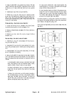
Page 137: ...s Required for Disassembly and Reassembly 1 2 in Socket Ratchet Wrench Torque Wrench 68 Nm 50 Ibs ft Soft Face Hammer Internal Retaining Ring Pliers Straight 2 3mm 090 in Tip External Retaining Ring Pliers Straight 1 8mm 070 in Tip Seal Driver or Similar Tool Petroleum Jelly Such as Vaseline Disassembly 1 Clamp the drive shaft end of the piston motor in a pro tected jaw vise with the cap screws up...

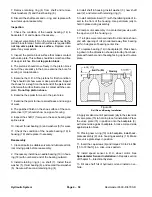
Page 138: ...ll parts in suitable solvent and lubricate all crit ical moving parts before reassembly 2 If necessary install new needle bearing 19 in hous ing 18 with numbered end of the bearing outward 3 Install retaining ring 4 on shaft 7 Install thrust washer 5 thrust bearing 6 and second thrust washer 5 Secure with second retaining ring 4 4 Install shaft in housing Install washer 3 new shaft seal 2 and reta...

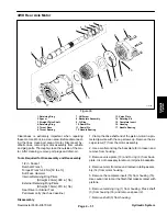
Page 139: ...bly and Reassembly 1 2 in Socket Ratchet Wrench Torque Wrench 68 Nm 50 Ibs ft Soft Face Hammer Internal Retaining Ring Pliers Straight 2 3mm 090 in Tip External Retaining Ring Pliers Straight 1 8mm 070 in Tip Seal Driver or Similar Tool Petroleum Jelly Such as Vaseline Disassembly 1 Clamp the drive shaft end of the piston motor in a pro tected jaw vise with the cap screws up Remove the six cap scr...

Page 140: ... bearing 17 in housing 16 and replace if necessary Reassembly 1 Clean all parts in suitable solvent and lubricate all crit ical moving parts before reassembly 2 If necessary install new needle bearing 17 in hous ing 16 with numbered end of the bearing outward 3 Install retaining ring 4 on shaft 3 Install thrust washer 5 thrust bearing 6 and second thrust washer 5 Secure with second retaining ring ...

Page 141: ...ate 2 Front body 12 Washer 22 O Ring 3 Drive gear assembly 13 Idler gear assembly 23 Plug 4 Wear plate 14 Key 24 Idler gear 5 Balance pressure seal 15 Gear 25 Rear body 6 Backup gasket 16 Middle body 26 Relief valve 7 Plug 17 Gear 27 Backup washer 8 Front plate assembly 18 Idler gear 28 O Ring 9 Copper washer 19 Key 29 O Ring 10 Cap Screw 20 Front adapter plate 30 Backplate assembly Hydraulic Syst...

Page 142: ...2 Place rear idler gear assembly 24 back into gear pocket and tap protruding end with soft face hammer to remove rear body 25 from the backplate assembly 30 or the rear adapter plate 21 13 Remove the wear plates 4 from front plate 8 front adapter plate 20 and rear adapter plate 21 14 Remove o rings 1 from front plate 8 adapter plates 20 21 and backplate 30 15 Remove backup gaskets 6 and balance pr...

Page 143: ...n coat of petroleum jelly to both milled gear pockets of front body 2 Slip body onto front plate 8 with half moon port cavities in body facing away from front plate NOTE The small half moon port cavity must be on the pressure side of pump 7 Place wear plate 4 on top of backup gasket 6 with bronze face up The side with the mid section cut away must be on suction side of pump 8 Dip drive gear assemb...

Page 144: ...lenoid 28 Watt 16 Relief cartridge 3000 PSI 4 Relief cartridge 2750 PSI 11 O ring 17 Cartridge N O poppet 5 Plug 12 Plug 18 Cartridge N C poppet 6 O ring 13 Cartridge N O poppet 19 Seal 7 Cartridge N C 2 20 Orifice 060 21 Orifice 040 1 Before removing any parts from the valve block park the machine on a level surface engage the parking brake lower the cutting units and stop the engine Re move key ...

Page 145: ...White Orange Rear Reels Mow Backlap Selector S4B Pink Blue Lift Lower 2 3 Torque to 15 in lb Apply Loctite 242 to threads Torque to 35 ft lb S4B VS1B S2B S1B S3B R1 PC1B Rear Valve Block RM6500 D Figure 34 1 Solenoid 20 Watt 7 Cartridge N C Spool 12 O ring 2 Rear Manifold Block 8 Solenoid 28 Watt 13 Relief cartridge 3000 PSI 3 O ring 9 Cartridge No Flow 14 Pilot check cartridge 4 Plug 10 Cartridge...

Page 146: ...3 S5B Black Red Lift Lower Selector 6 7 S6B Violet Red Lower 6 7 S7B Yellow Black Lift Lower 6 7 S8B Orange Blue Lift Lower 6 S9B Brown White Lift Lower 7 Torque to 15 in lb Apply Loctite 242 to threads Torque to 35 ft lb R1 PC1B S4B S6B S5B VS1B S2B S9B S8B S7B S1B S3B Figure 35 1 Cartridge N C spool 3 8 O ring 15 Orifice 040 2 Seal 9 Rear manifold block 16 Plug 3 Solenoid 20 Watt 10 Cartridge N ...

Page 147: ...ng or there may be water in the system 5 Clean and check for proper valve operation A Use clean mineral spirits to clean cartridge valve Submerge the valve in clean mineral spirits and use a probe to push the internal spool in and out 20 to 30 times to flush out contamination Mineral spirits does not affect the o ring material Particles as fine as talcum powder can affect the operation of high pre...

Page 148: ...y all parts Apply hydraulic oil to parts and install in the same order they were removed Disassembly NOTE Parts must be replaced as a kit Gears gear housing and bearing blocks cannot be serviced sepa rately Replace complete motor if these parts are dam aged or severly worn IMPORTANT The motor is run in at the factory to obtain precise parts tolerances Keep housing gears and bearings for each motor...

Page 149: ... groove in bearing block 3 Repeat for other bearing block O ring Replacement 1 Remove dowel pins 6 and O rings 5 from gear housing Clean O ring grooves 2 Apply a light coating of grease or petroleum jelly to O ring grooves in gear housing and install new O rings in each groove Reassembly 1 Put flange 3 on a flat surface with shaft seal facing down Make sure back side of flange is free of contami n...

Page 150: ... and head from cylinder barrel 5 Securely mount piston piston rod and head into vise and remove nut IMPORTANT Do not clamp vise jaws against smooth piston rod surface the piston rod will be come damaged 6 Remove piston 7 Remove all seals and O rings 8 Wash part in a safe solvent Dry parts with com pressed air DO NOT wipe them dry with a cloth or paper as lint and dirt may remain 9 Carefully inspec...

Page 151: ...d head from cylinder barrel 4 Securely mount piston piston rod and head into vise and remove nut Remove piston IMPORTANT Do not clamp vise jaws against smooth piston rod surface the piston rod will be come damaged 5 Remove all seals and O rings 6 Wash part in a safe solvent Dry parts with com pressed air DO NOT wipe them dry with a cloth or paper as lint and dirt may remain 7 Carefully inspect int...

Page 152: ...torted Unscrew collar 4 Grasp the clevis end of shaft and use a twisting and pulling motion to carefully extract piston shaft and head from barrel 5 Securely mount clevis end of shaft in a vise and re move lock nut from piston end of shaft Remove the pis ton Slide the head off of shaft 6 Remove and discard all seals and backup rings 7 Wash parts in cleaning solvent Dry parts with com pressed air D...

Page 153: ...nt clevis end of shaft in a vise and re move nut from piston end of shaft Remove piston Slide head off of shaft 6 Remove and discard all seals and backup rings 7 Wash the parts in cleaning solvent Dry parts with compressed air DO NOT wipe dry with a cloth or paper as lint and dirt may remain 8 Inspect internal surface of barrel for damage deep scratches out of round etc Inspect head shaft and pist...

Page 154: ...ollar 4 Grasp clevis end of shaft and use a twisting and pull ing motion to carefully extract piston shaft and head from barrel 5 Securely mount the clevis end of the shaft in a vise and remove the lock nut from the piston end of the shaft Remove the piston Slide the head off of the shaft 6 Remove and discard all seals and backup rings 7 Wash parts in cleaning solvent Dry parts with com pressed ai...

Page 155: ...e Plate 17 Link Drive Spacer 31 Seal Spacer 4 Spring 18 Plug 33 Face Seal 5 Alignment Pin 19 O Ring 34 Thrust Bearing 6 Isolation Manifold 20 Ball 35 Drive Plate 7 Metering Ring 21 Hex Nut 36 Special Bolt 8 Hex Drive Assembly 22 Port Cover 37 Upper Cover Jacket 9 Drive Link 23 O Ring 38 Retaining Plate 10 HSH Screw 24 Port Manifold 39 Retaining Plate Washer 11 Commutator Seal 25 Spring 40 Retainin...

Page 156: ... be a slip fit into the com ponents Use the minimum force necessary and maxi mum care when separating or assembling the components The steering valve has several components that are of brazed laminate construction These components have plates and parts bonded together permanently to form an integral component that cannot be disassembled Disassemble the steering valve only to the extent shown in th...

Page 157: ...disassembly of the steer ing valve study the relative positions of the alignment grooves on the side of the components in the assembly The relative alignment groove positions on the compo nents must be maintained at reassembly Fig 42 2 Use a slot type screwdriver or screwdriver socket to loosen the plug assembly one turn counterclockwise Fig 45 Do not remove the plug assembly 3 Remove the four nut...

Page 158: ... unit has two different length spring sets The set you have just removed from the port manifold are 3 4 in 19 mm long Keep this set of three springs separate from the next set of three springs to be removed 9 Inspect the springs for bent or distorted coils If a spring is broken or deformed all six springs in the unit should be replaced 10 Inspect the ground surfaces of the port manifold You should...

Page 159: ...of nicks and scoring 12 Remove the valve plate by lifting it from the isolation manifold Fig 52 13 Inspect the slot edges and ground surfaces If the valve plate shows nicks or scoring or the edges are not sharp it must be replaced NOTE The valve ring and valve plate are a matched set and must be replaced as a set Figure 50 Figure 51 Figure 52 Hydraulic System ...

Page 160: ...emoved from the port manifold 15 Inspect the springs for bent or distorted coils If a spring is broken or deformed all six springs in the unit must be replaced Fig 54 16 Remove the hex drive assembly from the drive link Fig 55 17 The pin in the hex drive assembly should not show wear and must be firmly pressed in place the sides of the hex and slot should not have grooves or scoring if the hex dri...

Page 161: ...should notice a normal polished pattern due to the rotation of the valve plate and on the opposite side a normal polished pattern due to the action of the commutator cover and commutator seal The holes and edges should be free of nicks The manifold surfaces should be free of nicks or scoring If the manifold has de veloped any of these conditions it must be replaced 21 Remove the two isolation mani...

Page 162: ... is evident 24 Remove the metering ring and discard the two seal rings Fig 60 If the metering ring bore is scored it should be replaced 25 The metering package components are held to gether with eleven hex socket head screws Lift the me tering package from the assembly and put it on a clean surface Fig 61 IMPORTANT Do not clamp the metering package in a vise as this could damage the components Fig...

Page 163: ...ig 63 Use a 3 32 in Allen wrench Inspect the screws for thread and socket damage and replace as necessary 28 Lift the commutator cover from the metering pack age Fig 64 29 Inspect the ground surfaces of the commutator cov er You should notice a normal polished pattern due to the rotation of the commutator If the cover has nicks burrs or scoring it must be replaced Figure 62 Figure 63 Figure 64 Hyd...

Page 164: ...ound plates pinned and bonded together as a permanent assembly that cannot be disassembled Inspect the ground sur faces of the commutator The holes and edges should be free of nicks The ground surfaces should be free of scoring The edges should be sharp NOTE The commutator and commutator ring are a matched set If either is worn or damaged the set must be replaced IMPORTANT Five alignment pins conn...

Page 165: ...clear ance with a feeler gauge Fig 69 The rotor lobe di rectly across from the rotor lobe tip being measured see pointer in Fig 69 must be centered between stator lobes during the measurement A rotor and stator that exceeds the maximum allowable tip clearance must be replaced Max rotor to stator tip clearance 0 003 in 0 08 mm 37 Remove the rotor set from the drive plate The drive plate side of the...

Page 166: ... must be replaced 40 Remove the face seal backup ring and face seal spacer from the upper cover plate Fig 72 Discard the face seal and backup ring Keep the metal spacer 41 Remove the thrust bearing and bearing spacer from the upper cover plate Fig 73 42 Inspect the thrust bearing for brinelling dents or spalling flaking if either exists or if one or more of the rolls are lost or broken replace the...

Page 167: ...be free of brinelling dents or spalling flaking If it is damaged the upper cover plate must be replaced 44 Slide the seal from the jacket tube Fig 75 If the seal is worn or damaged it must be replaced 45 Remove the input shaft and snap ring sliding it out of the upper cover end of the assembly Fig 76 46 Inspect the input shaft serrations threads and flats for grooves wear or damage Figure 74 Figur...

Page 168: ...d 48 Inspect the bushing at the top of the cover jacket for wear or damage If bushing replacement is neces sary put the upper cover jacket in a vise Use a pliers or punch to straighten the crimped areas on the bushing end of the jacket tube Fig 78 IMPORTANT Hold the steering tube in a soft jaw vise Be careful not to damage the steering tube 49 Use a bearing puller to remove the bushing Fig 79 Figu...

Page 169: ...elmaster 6500 D 6700 D Page 4 81 Hydraulic System 50 Remove the nuts holding the four bolts to the fixture and remove the bolts Fig 80 Check the bolt threads for wear or damage Figure 80 Hydraulic System ...

Page 170: ...th four 5 16 24 UNF nuts Tighten the nuts to secure the as sembly to the fixture but loose enough to turn the bolts and facilitate stacking of components 2 If the bushing was removed from the upper cover and jacket for replacement press a new bushing into the up per end of the jacket tube with the recessed end of the bushing toward the jacket tube Use an arbor press or the wood handle end of a ham...

Page 171: ...r against the re cessed face of the retainer plate 5 Install the snap ring onto the input shaft if it was re moved Fig 85 6 Slide the input shaft into the upper cover end of the upper cover jacket and through the bushing until the retaining ring bottoms against the washer Make sure the washer bottoms against the retainer plate recessed face and the retainer plate seats against the end of the jacke...

Page 172: ... face of the upper cover plate input shaft and face seal Fig 88 9 Assemble the seal backup ring and face seal onto the seal spacer Fig 89 10 Install the face seal backup ring and spacer assem bly over the end of the input shaft and onto the upper cover plate Fig 90 Figure 88 Figure 89 Figure 90 ...

Page 173: ...he eleven hex socket head screw re lief slots are aligned with the tapped holes in the drive plate Fig 91 12 Apply a small amount of clean multi purpose grease to the spacer and insert it into the drive slot in the rotor Fig 92 The grease will aid in retaining the spacer during other assembly procedures 13 Put the commutator on top of the rotor Be sure the correct surface Fig 93 is towards the rot...

Page 174: ...MPORTANT Make sure the five alignment pins are pressed below the surface of the commutator 15 Put a few drops of oil into each recess in the commu tator Fig 95 16 Put the commutator ring either side up on top of the stator Fig 96 Align the commutator ring screw re cesses with the stator screw slots Figure 94 Figure 95 Figure 96 ...

Page 175: ...leven hex socket head cap screws The next two procedures are a method of achieving the concentricity 19 Put the metering ring on a hard flat surface Put the assembled metering package into the metering ring with the commutator cover down so the drive plate is partial ly out of the metering ring Fig 99 A suitable wood block under the metering package will hold it in this posi tion Put one piece of ...

Page 176: ...face Push down on the metering pack age until the drive plate is on the flat surface Be sure the cap screws are loose enough to allow the commutator ring and drive plate to align themselves concentrically in the metering ring bore Gradually tighten the eleven cap screws following the sequence shown in Figure 101 at least twice until a final torque of 11 13 in lb 1 24 1 47 Nm is reached Fig 101 and...

Page 177: ...assembly and concentricity procedures 24 Apply clean multi purpose grease to the metering ring seal ring Put the seal ring into position in the meter ing ring seal groove opposite to the end with the align ment pin holes Stack the metering ring into place over the four bolts with the seal ring towards the upper cover plate Make sure an alignment pin hole on the metering ring is in line with and on...

Page 178: ... Fig 106 26 Lightly grease the roller thrust bearing and put it on the upper cover plate inside the bearing spacer Fig 107 27 Inspect the exposed face of the drive plate making sure it is clean and lint free Apply a small amount of clean multi purpose grease on the drive plate Fig 108 Figure 106 Figure 107 Figure 108 ...

Page 179: ...ing When properly seated the metering package will be below the surface of the meter ing ring 29 Apply clean multi purpose grease on the new com mutator seal and put it into the commutator cover seal groove Fig 110 The rubber portion the softer side of the seal with the yellow mark must be put into the seal groove 30 Apply clean multi purpose grease to the metering ring seal ring Put the seal ring...

Page 180: ...ng ring aligning the grooves on the side of the manifold with the grooves on the side of the upper cover plate Fig 113 Align the alignment pin holes with the alignment pins in the metering ring The isolation manifold surface without the recessed slots must be toward the metering ring 33 Install two alignment pins into the isolation manifold Fig 114 Figure 112 Figure 113 Figure 114 ...

Page 181: ... the valve ring over the bolts and alignment pins with the seal ring facing the isolation manifold Fig 116 IMPORTANT Be sure the seal ring is seated correct ly after the valve ring is assembled 36 Put the hex drive assembly pin side up through the hole in the isolation manifold Fig 117 the slot in the hex drive must be engaged with the SMALL tang of the drive link Turn the input shaft to assist th...

Page 182: ... small cavity and the words port side centrally below it Fig 118 must be placed over the spring and spring recess in the isolation manifold at the top 12 o clock position as shown Fig 118 and 101 Adjust the valve plate position radially to centralize the spring slots over the springs and the spring recesses in the isolation manifold IMPORTANT The unit will not function if the valve plate is not po...

Page 183: ...ble the port manifold with the springs toward the valve plate Fig 122 Be careful not to pinch a spring during instal lation The two alignment pins in the valve plate will en gage the holes in the port manifold The pin on the hex drive assembly must engage the center hole in the port manifold 41 Install a new o ring on the plug Insert the check ball hole in the port cover Be sure the ball is seated...

Page 184: ...e to the four o rings and seal ring Put the new o rings and seal ring into their proper location in the port cover Fig 124 43 Align a groove on the side of the port cover with the grooves on the side of the port manifold and put the port cover into position Fig 125 Figure 124 Figure 125 ...

Page 185: ...ock nuts onto the bolts Tighten each nut gradually until resistance is felt Fig 126 Tighten to a torque of 20 24 ft lb 27 33 Nm in the sequence shown Fig 127 45 Tighten the plug to a torque of 8 12 ft lb 11 16 Nm Fig 128 Figure 126 Figure 127 Figure 128 Hydraulic System ...

Page 186: ...nspection of the relative groove posi tions on the side of the unit Fig 42 Components of the steering valve with alignment grooves must be as sembled so that their alignment grooves are positioned as illustrated for the valve to function correctly Fig 42 Disassemble and correct the assembly if necessary 48 Remove the four nuts holding the unit to the fixture and remove the unit Fig 130 Figure 129 ...

Page 187: ...lter Head 31 O Ring 6 Plastic Plug 19 Hydraulic 90_ Fitting 32 Tee Fitting 7 O Ring 20 Filter Hose 33 O Ring 8 Dipstick 21 Element 34 Suction Strainer 9 Screen Filter 22 Suction Hose 35 Breather Adapter 10 O Ring 23 Clamp 36 O Ring 11 Hydraulic Fitting 24 Hose Fitting 37 Adapter 12 O Ring 25 Fitting Cap 38 O Ring 13 Return Hose 26 Drain Tube 39 Return Steering Tube Inspecting Reservoir Parts 1 Cle...

Page 188: ...reservoir NOTE Use biodegradable fluid such as Mobil EAL 224H for this step if you are changing to this type of fluid Use only hydraulic fluids specified see Specifications section of this chapter Other fluids could cause system damage 6 Disconnect fuel stop solenoid electrical connector to prevent engine from starting 7 Turn ignition key switch to engage starter for ten 10 seconds to prime pump R...

Page 189: ...rk in a clean area Before dis connecting the hydraulic lines clean the port area of the steering control unit Before disassembly drain the oil then plug the ports and thoroughly clean the exterior During repairs always protect machined surfaces 1 Remove the seven capscrews and disassemble the steering control unit as shown Fig 134 2 Remove the plug and manual steering check valves Hydraulic System...

Page 190: ...de screwdriver to carefully pry the dust seal from the housing Be careful to not damage the dust seal seat 7 Remove the pin that holds the spool and sleeve together Fig 136 8 Carefully slide the spool out of the sleeve The springs and retaining ring will stay with the spool as it is removed 9 Remove the retaining ring and springs The centering springs are under tension Remove the retaining ring ca...

Page 191: ... on the gerotor end of the sleeve D Fit the quad seal into its seat through the input end of the housing Be sure the seal is not twisted E Remove the sleeve and bearing race 2 Lubricate and install the dust seal See Figure 137 for correct seal orientation 3 Install the centering springs in the spool Fig 136 It is best to install the two flat pieces first Next install the curved pieces three at a t...

Page 192: ...n the drive engages the pin 14 Lubricate and install a new o ring seal in the groove in the wear plate 15 Install the gerotor and align the screw holes 16 Lubricate and install a new o ring seal in the groove in the gerotor ring 17 Lubricate and install a new o ring and seal ring in the groove in the gerotor star 18 Install the spacer 19 Install the end cap and seven capscrews Tighten the capscrew...

Page 193: ...eelmaster 6700 D 24 Fault Memory and Retrieval 26 Leak Detector Operation 26 1 Checking Leak Detector 26 1 Leak Detector Troubleshooting 26 5 Understanding the Controllers 27 Understanding the Diagnostic Lamps 28 Starting Problems 29 General Run and Transport Problems 30 Cutting Unit Operation Problems 32 ELECTRICAL SYSTEM QUICK CHECKS 33 Battery 33 Charging System Test 33 Voltage Drop Testing 32 ...

Page 194: ... ORG WATER TEMPSENSOR 3B 1P 1R 1D 2S 1C BLACK RED ORANGE BLACK ORANGE WHITE ORANGE BLUE YELLOW BLACK BLACK 2L 1A 1J 1K 1L 1M COMMUNICATION PORT BLACK PINK WHITE VCC 10A 3A 10A 4A 10A 1A START GREEN BLACK BLUE WHITE RED BLACK PINK BLACK 3K 3J 3P 3R 3S ORANGE BLUE GREEN PINK BLACK RS232 RX RS232 TX RS232 GND RED WHITE BLACK WHITE 2J SPEED SENSOR GRAY 2P YELLOW YELLOW YELLOW 2F 3F BACKLAP REAR SWITCH...

Page 195: ...1R 1D 2S 1C BLACK RED ORANGE BLACK ORANGE WHITE ORANGE BLUE YELLOW BLACK BLACK 2L 1A 1J 1K 1L 1M COMMUNICATION PORT BLACK PINK WHITE VCC 10A 3A 10A 4A 10A 1A GREEN BLACK BLUE WHITE RED BLACK PINK BLACK 3K 3J 3P 3R 3S ORANGE BLUE GREEN PINK BLACK RS232 RX RS232 TX RS232 GND RED WHITE BLACK WHITE 2J SPEED SENSOR GRAY 2P YELLOW YELLOW 2F 3F BACKLAP REAR SWITCH BACKLAP FRONT SWITCH BACKLAP SWITCH BLAC...

Page 196: ... C A B ORG WATER TEMPSENSOR 3B 1P 1R 1D 2S 1C BLACK RED ORANGE BLACK ORANGE WHITE ORANGE BLUE YELLOW BLACK 2L 1A 1J 1K 1L 1M COMMUNICATION PORT BLACK PINK WHITE VCC 10A 10A 10A START GREEN BLACK BLUE WHITE RED BLACK PINK BLACK 3K 3J 3P 3R 3S ORANGE BLUE GREEN PINK BLACK RS232 RX RS232 TX RS232 GND RED WHITE BLACK WHITE 2J SPEED SENSOR GRAY 2P YELLOW YELLOW YELLOW 2F 3F BACKLAP REAR SWITCH BACKLAP ...

Page 197: ...K RED ORANGE BLACK ORANGE WHITE ORANGE BLUE YELLOW BLACK BLACK 2L 1A 1J 1K 1L 1M COMMUNICATION PORT BLACK PINK WHITE VCC 10A 3A 10A 4A 10A 1A START GREEN BLACK BLUE WHITE RED BLACK PINK BLACK 3K 3J 3P 3R 3S ORANGE BLUE GREEN PINK BLACK RS232 RX RS232 TX RS232 GND RED WHITE BLACK WHITE 2J SPEED SENSOR GRAY 2P YELLOW YELLOW YELLOW 2F 3F BACKLAP REAR SWITCH BACKLAP FRONT SWITCH BACKLAP SWITCH BLACK B...

Page 198: ...1R 1D 2S 1C BLACK RED ORANGE BLACK ORANGE WHITE ORANGE BLUE YELLOW BLACK BLACK 2L 1A 1J 1K 1L 1M COMMUNICATION PORT BLACK PINK WHITE VCC 10A 3A 10A 4A 10A 1A START GREEN BLACK BLUE WHITE RED BLACK PINK BLACK 3K 3J 3P 3R 3S ORANGE BLUE GREEN PINK BLACK RS232 RX RS232 TX RS232 GND RED WHITE BLACK WHITE 2J SPEED SENSOR GRAY 2P YELLOW YELLOW YELLOW 2F 3F BACKLAP REAR SWITCH BACKLAP FRONT SWITCH BACKLA...

Page 199: ... BLACK RED ORANGE BLACK ORANGE WHITE ORANGE BLUE YELLOW BLACK BLACK 2L 1A 1J 1K 1L 1M COMMUNICATION PORT BLACK PINK WHITE VCC 10A 3A 10A 4A 10A 1A START GREEN BLACK BLUE WHITE RED BLACK PINK BLACK 3K 3J 3P 3R 3S ORANGE BLUE GREEN PINK BLACK RS232 RX RS232 TX RS232 GND RED WHITE BLACK WHITE 2J SPEED SENSOR GRAY 2P YELLOW YELLOW YELLOW 2F 3F BACKLAP REAR SWITCH BACKLAP FRONT SWITCH BACKLAP SWITCH BL...

Page 200: ...R 1D 2S 1C BLACK RED ORANGE BLACK ORANGE WHITE ORANGE BLUE YELLOW BLACK BLACK 2L 1A 1J 1K 1L 1M COMMUNICATION PORT BLACK PINK WHITE VCC 10A 3A 10A 4A 10A 1A START GREEN BLACK BLUE WHITE RED BLACK PINK BLACK 3K 3J 3P 3R 3S ORANGE BLUE GREEN PINK BLACK RS232 RX RS232 TX RS232 GND RED WHITE BLACK WHITE 2J SPEED SENSOR GRAY 2P YELLOW YELLOW 2F 3F BACKLAP REAR SWITCH BACKLAP FRONT SWITCH BACKLAP SWITCH...

Page 201: ...ENSOR 3B 1P 1R 1D 2S 1C BLACK RED ORANGE BLACK ORANGE WHITE ORANGE BLUE YELLOW BLACK BLACK 2L 1A 1J 1K 1L 1M COMMUNICATION PORT BLACK PINK WHITE VCC 10A 3A 10A 4A 10A 1A START GREEN BLACK BLUE WHITE RED BLACK PINK BLACK 3K 3J 3P 3R 3S ORANGE BLUE GREEN PINK BLACK RS232 RX RS232 TX RS232 GND RED WHITE BLACK WHITE 2J SPEED SENSOR GRAY 2P YELLOW YELLOW 2F 3F BACKLAP REAR SWITCH BACKLAP FRONT SWITCH B...

Page 202: ...Reelmaster 6500 D 6700 D Page 5 8 2 Electrical System Rev C This page is intentionally blank ...

Page 203: ...GE WHITE ORANGE BLUE YELLOW BLACK BLACK 2L 1A 1J 1K 1L 1M COMMUNICATION PORT BLACK PINK WHITE VCC 10A 3A 10A 4A 10A 1A START GREEN BLACK BLUE WHITE RED BLACK PINK BLACK 3K 3J 3P 3R 3S ORANGE BLUE GREEN PINK BLACK RS232 RX RS232 TX RS232 GND RED WHITE BLACK WHITE 2J SPEED SENSOR GRAY 2P YELLOW YELLOW 2F 3F BACKLAP REAR SWITCH BACKLAP FRONT SWITCH BACKLAP SWITCH BLACK BLUE WHITE GROUND BATTERY POWER...

Page 204: ...BLACK ORANGE WHITE ORANGE BLUE YELLOW BLACK BLACK 2L 1A 1J 1K 1L 1M COMMUNICATION PORT BLACK PINK WHITE VCC 10A 3A 10A 4A 10A 1A START GREEN BLACK BLUE WHITE RED BLACK PINK BLACK 3K 3J 3P 3R 3S ORANGE BLUE GREEN PINK BLACK RS232 RX RS232 TX RS232 GND RED WHITE BLACK WHITE 2J SPEED SENSOR GRAY 2P YELLOW YELLOW 2F 3F BACKLAP REAR SWITCH BACKLAP FRONT SWITCH BACKLAP SWITCH BLACK BLUE WHITE GROUND BAT...

Page 205: ...E WHITE ORANGE BLUE YELLOW BLACK BLACK 2L 1A 1J 1K 1L 1M COMMUNICATION PORT BLACK PINK WHITE VCC 10A 3A 10A 4A 10A 1A START GREEN BLACK BLUE WHITE RED BLACK PINK BLACK 3K 3J 3P 3R 3S ORANGE BLUE GREEN PINK BLACK RS232 RX RS232 TX RS232 GND RED WHITE BLACK WHITE 2J SPEED SENSOR GRAY 2P YELLOW YELLOW 2F 3F BACKLAP REAR SWITCH BACKLAP FRONT SWITCH BACKLAP SWITCH BLACK BLUE WHITE GROUND BATTERY POWER ...

Page 206: ... BLACK ORANGE WHITE ORANGE BLUE YELLOW BLACK BLACK 2L 1A 1J 1K 1L 1M COMMUNICATION PORT BLACK PINK WHITE VCC 10A 3A 10A 4A 10A 1A START GREEN BLACK BLUE WHITE RED BLACK PINK BLACK 3K 3J 3P 3R 3S ORANGE BLUE GREEN PINK BLACK RS232 RX RS232 TX RS232 GND RED WHITE BLACK WHITE 2J SPEED SENSOR GRAY 2P YELLOW YELLOW 2F 3F BACKLAP REAR SWITCH BACKLAP FRONT SWITCH BACKLAP SWITCH BLACK BLUE WHITE GROUND BA...

Page 207: ...NGE WHITE ORANGE BLUE YELLOW BLACK BLACK 2L 1A 1J 1K 1L 1M COMMUNICATION PORT BLACK PINK WHITE VCC 10A 3A 10A 4A 10A 1A START GREEN BLACK BLUE WHITE RED BLACK PINK BLACK 3K 3J 3P 3R 3S ORANGE BLUE GREEN PINK BLACK RS232 RX RS232 TX RS232 GND RED WHITE BLACK WHITE 2J SPEED SENSOR GRAY 2P YELLOW YELLOW 2F 3F BACKLAP REAR SWITCH BACKLAP FRONT SWITCH BACKLAP SWITCH BLACK BLUE WHITE GROUND BATTERY POWE...

Page 208: ...ACK ORANGE WHITE ORANGE BLUE YELLOW BLACK BLACK 2L 1A 1J 1K 1L 1M COMMUNICATION PORT BLACK PINK WHITE VCC 10A 3A 10A 4A 10A 1A START GREEN BLACK BLUE WHITE RED BLACK PINK BLACK 3K 3J 3P 3R 3S ORANGE BLUE GREEN PINK BLACK RS232 RX RS232 TX RS232 GND RED WHITE BLACK WHITE 2J SPEED SENSOR GRAY 2P YELLOW YELLOW 2F 3F BACKLAP REAR SWITCH BACKLAP FRONT SWITCH BACKLAP SWITCH BLACK BLUE WHITE GROUND BATTE...

Page 209: ...Reelmaster 6500 D 6700 D Page 5 15 Electrical System Reelmaster 6700 D Controller 2 Electrical System ...

Page 210: ...Reelmaster 6500 D 6700 D Page 5 16 Electrical System 20 Amp Fuse Ignition Switch Circuits Reelmaster 6700 D Controller 2 ...

Page 211: ...Reelmaster 6500 D 6700 D Page 5 17 Electrical System 15 Amp Fuse Controller 2 Power Circuits Reelmaster 6700 D Controller 2 Electrical System ...

Page 212: ... F S Pin Labeling on Controller Connector 2A OUTPUTS INPUTS 3C 2B 3M 1S 1B 1E 1F 1H 2C 2G 2D 3E 2E 3G 1N 1G 2K 3B 1P 1R 1D 2S 1C 2L 1A 1J 1K 1L 1M 3K 3J 3P 3R 3S 2J 2P 2F 3F GROUND BATTERY POWER 3A 3N 2H 3H 3L SOLID STATE CONTROLLER 92 5720 2M NOTE The smaller connector is phyisically labeled A F but the controller diagram refers to these connections as L S ...

Page 213: ...mutli meter when testing electrical circuits The high imped ance internal resistance of a digital meter will ensure that excess current is not allowed through the meter Ex cess current can cause damage to a circuit that is not de signed to carry it Figure 1 Inductive Ammeter AC DC Current Transducer Hall Effect Use this tool connected to a Digital multimeter for doing current draw tests This tool ...

Page 214: ...ctor located inside the R H console to help the user verfiy correct electrical functions of the machine Data Logt System The data log system controller is connected to the wiring harness connector near the electronic control unit ECU This device can record machine data while it is in operation to help your Toro Distributor diagnose intermittent problems Decal Diagnostic ACE Display Figure 3 Figure...

Page 215: ...nctioning correctly Check electrical connections input fuses and diagnos tic light bulb to determine malfunction Make sure loop back connector is secured to wire harness connector Diagnostic ACE Display The RM 6500 D is equipped with an electronic control ler which controls most machine functions The control ler determines what function is required for various input switches i e seat switch key sw...

Page 216: ...with an ohm meter Replace any defec tive switches and repair any defective wiring The Diagnostic ACE also has the ability to detect which output solenoids or relays are turned on This is a quick way to determine if a machine malfunction is electrical or hydraulic To verify output function 1 Park machine on a level surface lower the cutting units stop the engine and engage the parking brake 2 Open ...

Page 217: ... those functions If the machine problem appears to be with one of these functions be certain to check the elec trical circuit with a volt ohm meter to verify that no elec trical problem exists to these functions If each input switch is in the correct position and func tioning correctly but the output LED s are not correctly illuminated this indicates an ECU problem If this oc curs contact your Tor...

Page 218: ...ON position this indicates that the elec tronic controller is not operating Possible causes are 1 Loopback connector under control panel cover is not connected 2 The electronic controller light is burned out 3 Fuses are blown 4 Electronic controller not functioning correctly Check electrical connections input fuses and diagnos tic light bulb to determine malfunction Make sure loop back connector i...

Page 219: ... the ON position but do not start machine Note The red text on the overlay decal refers to input switches and the green text refers to outputs Figure 11 1 Diagnostic ACE 1 5 The inputs displayed LED on lower right column of the Diagnostic ACE should be illuminated If outputs displayed LED is illuminated press and release the toggle button on Diagnostic ACE to change LED to in puts displayed Do not...

Page 220: ...The Diagnostic ACE displays must not be left connected to the machine It is not designed to withstand the environment of the machine s ev ery day use When done using Diagnostic ACE dis connect them from the machine and reconnect loopback connectors to harness connectors Ma chine will not operate without loopback connectors installed on harnesss Store Diagnostic ACE in dry secure location in shop n...

Page 221: ... cutting units it means that a leak has been detected On the Reelmaster trac tion unit the red light on the steering console will also blink indicating the Reelmaster ECU has shut off the cutting unit s Figure 11a 1 Alarm 1 Checking Leak Detector Operation The operation of the TurfDefender should be checked if any of the following conditions occur Note The hand held Diagnostic ACE can be used to i...

Page 222: ... it is best to check when cool 1 When toggling input a LED should display any of the following problems diagnosed by the TurfDefender Oil level low Position machine on a level surface and fill to proper level Oil level high Position machine on a level sur face and remove excess oil until proper level is at tained Oil too hot Allow machine to cool and clean any debris from oil cooler Air leak in sy...

Page 223: ...ent to analyze system problems Sometimes a false leak detect can occur when the TurfDefender erroneously concludes that a hydraulic leak has occurred The Turf Defender continually monitors several independent functions to determine if an oil leak is occurring These functions are influenced by various external factors such as ambient temperature variations between machines and machine operating pra...

Page 224: ...is too hot 5 LED lit if system air leak has been detected 6 One or two LED s lit displaying relative position of the Turfdefender s internal float 7 Inputs Displayed LED ON Red Normal Operation a Oil Level OK LED lit b 1 or 2 LED s lit on left column Using Inputs Displayed Red Text 4 5 6 a b Figure 11e Normal Operation a Valve ON LED lit steadily b Self Diagnostic LED lit steadily c DATA LINE LED ...

Page 225: ...cap is loose Tighten Operator is making severe left turns Slow down while turning Oil level is near the ADD mark Add oil to FULL mark Operator jiggles traction while waiting Leave pedal in Neutral while waiting Solenoid valve not sealing Check if loose replace if defective No beep occurs at start up Alarm wires are reversed or disconnected Connect red to black to TurfDefender 4 pin connector is un...

Page 226: ...Reelmaster 6500 D 6700 D Page 5 26 6 Electrical System Rev B This page is blank ...

Page 227: ...er controller and or leak detector by the CAN bus Fault Identification Operator Warning S Flashing reel control lamp red on steering tower and or diagnostic lamp green under control console Diagnostics S Do troubleshooting by connecting one of the follow ing devices to the loopback connector Diagnostic ACE with the correct overlay TOROPC and a personal computer Data Log Turf Defender Leak Detector...

Page 228: ... a reel speed of less than 50 RPM Controller 2 Secondary Fault Identification Operator Warning RM6700 D only The diagnostic lamp green under the control console will stay steady if 1 Controller 2 program is successfully loaded from 1 and read to operate all O K A flashing reel control lamp red on steering tower AND a flashing diagnostic lamp green under control console indicates 1 Controller 2 sen...

Page 229: ...d ÁÁÁÁÁÁÁÁÁÁÁÁÁÁÁÁÁ ÁÁÁÁÁÁÁÁÁÁÁÁÁÁÁÁÁ ÁÁÁÁÁÁÁÁÁÁÁÁÁÁÁÁÁ Clean and tighten or repair as necessary ÁÁÁÁÁÁÁÁÁÁÁÁÁÁÁÁÁ ÁÁÁÁÁÁÁÁÁÁÁÁÁÁÁÁÁ ÁÁÁÁÁÁÁÁÁÁÁÁÁÁÁÁÁ Faulty wiring at starter ÁÁÁÁÁÁÁÁÁÁÁÁÁÁÁÁÁ ÁÁÁÁÁÁÁÁÁÁÁÁÁÁÁÁÁ ÁÁÁÁÁÁÁÁÁÁÁÁÁÁÁÁÁ Repair wiring ÁÁÁÁÁÁÁÁÁÁÁÁÁÁÁÁÁ ÁÁÁÁÁÁÁÁÁÁÁÁÁÁÁÁÁ Loose starter mounting bolts ÁÁÁÁÁÁÁÁÁÁÁÁÁÁÁÁÁ ÁÁÁÁÁÁÁÁÁÁÁÁÁÁÁÁÁ Clean mounting surface and tighten bolts ÁÁÁÁÁÁÁÁÁÁÁÁÁÁ...

Page 230: ... fast enough ÁÁÁÁÁÁÁÁÁÁÁÁÁÁÁÁÁ ÁÁÁÁÁÁÁÁÁÁÁÁÁÁÁÁÁ ÁÁÁÁÁÁÁÁÁÁÁÁÁÁÁÁÁ ÁÁÁÁÁÁÁÁÁÁÁÁÁÁÁÁÁ Check battery and cable connections Charge battery Replace battery if it won t hold accept a charge Repair wiring if necessary ÁÁÁÁÁÁÁÁÁÁÁÁÁÁÁÁÁÁ ÁÁÁÁÁÁÁÁÁÁÁÁÁÁÁÁÁÁ Run solenoid faulty ÁÁÁÁÁÁÁÁÁÁÁÁÁÁÁÁÁ ÁÁÁÁÁÁÁÁÁÁÁÁÁÁÁÁÁ Replace run solenoid ÁÁÁÁÁÁÁÁÁÁÁÁÁÁÁÁÁÁ ÁÁÁÁÁÁÁÁÁÁÁÁÁÁÁÁÁÁ ÁÁÁÁÁÁÁÁÁÁÁÁÁÁÁÁÁÁ Problem is not e...

Page 231: ...aked seat cushion Test seat switch and replace if faulty Check seat switch wiring and repair if faulty ÁÁÁÁÁÁÁÁÁÁÁÁÁÁÁÁÁ ÁÁÁÁÁÁÁÁÁÁÁÁÁÁÁÁÁ ÁÁÁÁÁÁÁÁÁÁÁÁÁÁÁÁÁ ÁÁÁÁÁÁÁÁÁÁÁÁÁÁÁÁÁ ÁÁÁÁÁÁÁÁÁÁÁÁÁÁÁÁÁ ÁÁÁÁÁÁÁÁÁÁÁÁÁÁÁÁÁ Traction neutral switch circuit closed ÁÁÁÁÁÁÁÁÁÁÁÁÁÁÁÁÁ ÁÁÁÁÁÁÁÁÁÁÁÁÁÁÁÁÁ ÁÁÁÁÁÁÁÁÁÁÁÁÁÁÁÁÁ ÁÁÁÁÁÁÁÁÁÁÁÁÁÁÁÁÁ ÁÁÁÁÁÁÁÁÁÁÁÁÁÁÁÁÁ ÁÁÁÁÁÁÁÁÁÁÁÁÁÁÁÁÁ Check traction neutral switch adjustment a...

Page 232: ... faulty Check seat switch wiring and repair if faulty Battery Does Not Charge Cause Correction ÁÁÁÁÁÁÁÁÁÁÁÁÁÁÁÁÁÁ ÁÁÁÁÁÁÁÁÁÁÁÁÁÁÁÁÁÁ Alternator belt slipping ÁÁÁÁÁÁÁÁÁÁÁÁÁÁÁÁÁ ÁÁÁÁÁÁÁÁÁÁÁÁÁÁÁÁÁ Adjust belt tension ÁÁÁÁÁÁÁÁÁÁÁÁÁÁÁÁÁÁ ÁÁÁÁÁÁÁÁÁÁÁÁÁÁÁÁÁÁ ÁÁÁÁÁÁÁÁÁÁÁÁÁÁÁÁÁÁ Faulty wiring ÁÁÁÁÁÁÁÁÁÁÁÁÁÁÁÁÁ ÁÁÁÁÁÁÁÁÁÁÁÁÁÁÁÁÁ ÁÁÁÁÁÁÁÁÁÁÁÁÁÁÁÁÁ Check and repair wiring ÁÁÁÁÁÁÁÁÁÁÁÁÁÁÁÁÁÁ ÁÁÁÁÁÁÁÁÁÁÁÁÁÁÁÁÁÁ...

Page 233: ...at it is ca pable of Tool required Digital Multimeter DC volts setting Test instructions Connect the positive multimeter test lead on the positive Battery Post and negative lead on the negative Battery Post Leave test leads con nected and start engine and run at 2000 RPM minimum Test results should be At least 1 volt over Open Circuit test results Example Open Circuit Test results 12 5v Charging S...

Page 234: ... per instructions in Operator s Manu al and record the final results Typical specifications for systems without resistors of Glow Plugs Amps Draw 10 2 20 Amps 3 30 Amps 4 40 Amps Individual Glow Plug resistance all models 3 4 Ohms cold Starting System Test This is an excellent test to use when a slow crank no start problem is encountered It will tell you if the prob lem is due to an electrical ope...

Page 235: ... continuity check NOTE Electrical troubleshooting of any 12 Volt power connection can also be performed through voltage drop tests without disconnection of the component When testing electrical components for conti nuity with a volt ohm meter or continuity tes ter make sure that power to the circuit has been disconnected Ignition Key Switch The ignition key switch has three positions OFF START and...

Page 236: ...om the alternator to prevent damage to the electrical system 1 Figure 17 1 Electronic Control Unit Located behind access panel below seat Seat Switch The seat switch is a proximity type normally open NO reed switch that closes when the operator is on the seat With the operator on the seat the magnet on the bottom of the seat activates the reed switch causing it to close and complete the circuit 1 ...

Page 237: ...Figure 19 1 Traction neutral switch Cutting Unit Down Sensor s The cutting unit down switch is a normally open NO reed switch located on the left front lift arm that closes when the lift arm is in the lowered position As the lift arm is lowered a magnet in the lift arm causes the reed switch to close and complete the circuit NOTE The Reelmaster 6700 D also has sensors on each rear outboard lift ar...

Page 238: ...e should be indications that the switch is opening and closing With the joystick in the neutral position there should be no continuity across the terminals 1 Figure 21 Reelmaster 6500 D shown 1 Joystick with switches Enable Disable Switch es Test the Enable Disable switch by disconnecting the wires from the switch and connecting a continuity tester across the terminals of the switch With the switc...

Page 239: ...cross terminals 4 and 5 With the switch in the REAR position away from key way tester should show continuity across terminals 5 and 6 Terminals on switch Wire color 1 Not used 2 Not used 3 Not used 4 Blue 5 Black 6 White 1 Figure 23 1 Backlap switch Start Relay To test the relay disconnect the relay wire connector and install a continuity tester between the relay termi nals terminals 30 and 87 The...

Page 240: ...r from bat tery If the light glows check for power from ignition switch by moving to terminal 3 3 Glow plug test A Warm up the glow plugs by cycling the glow sys tem two times then check for total draw of all four 4 glow plugs if draw is 48 amps all four 4 are OK if draw is 36 amps then one 1 is faulty if draw is 24 amps then two 2 are faulty if draw is 12 amps then three 3 are faulty if draw is 0...

Page 241: ... fully extending and retracting 1 Figure 26 1 Fuel stop ETR solenoid Engine Oil Pressure Switch The switch is normally closed NC and opens with pres sure The switch opens at approximately 8 psi 1 Turn ignition key switch ON Oil pressure lamp should be on If lamp is not on 1 Disconnect wire from switch and touch wire to a good ground such as the engine block 2 If lamp comes on replace switch 3 If l...

Page 242: ...ch is in the RUN position with the engine not running or if the charging circuit is not operating properly during operation Glow Light The glow light should be on when the ignition switch is in the ON position The glow system runs off of a timer relay Temperature Light The temperature light should come on only if the high temperature shut down switch has stopped the engine coolant temperature abov...

Page 243: ...pletely down empty position resistance should be 240 260 ohms With arm completely up full position resistance should be 29 34 ohms NOTE Bend float arm if necessary to get proper gauge reading for a 1 2 full tank Make sure the sending unit is completely dry no fuel on it before testing Perform test away from fuel tank to prevent an explosion or fire from sparks 1 Figure 28 1 Fuel gauge sender Elect...

Page 244: ...moothly but does not retract when 12 V D C is applied to solenoid leads replace solenoid coil 5 If valve still does not retract after replacing solenoid coil replace the valve NOTE To do a quick test without removing solenoid valve hold a screwdriver to top of affected valve When solenoid is energized screw driver should be attracted to valve stem due to magnetism from energized sole noid This tes...

Page 245: ...All S6A Yellow Black Lift Lower 4 5 S7A Yellow White Lift Lower 1 VS1A Torque to 15 in lb Apply Loctite 242 to threads Torque to 35 ft lb S4A S7A S1A S3A S2A S5A S6A R2A R1A PC1A Front Valve Block Lowering speed adjustment valve for 4 5 cutting units 20 21 Figure 31 1 Solenoid 20 Watt 8 Cartridge 14 Plug 2 Pilot check cartridge 9 Cartridge N O 15 O ring 3 Front manifold block 10 Solenoid 28 Watt 1...

Page 246: ...ctor S3B White Orange Rear Reels Mow Backlap Selector S4B Pink Blue Lift Lower 2 3 Torque to 15 in lb Apply Loctite 242 to threads Torque to 35 ft lb S4B VS1B S2B S1B S3B R1 PC1B Rear Valve Block RM6500 D Figure 32 1 Solenoid 20 Watt 7 Cartridge N C Spool 12 O ring 2 Rear Manifold Block 8 Solenoid 28 Watt 13 Relief cartridge 3000 PSI 3 O ring 9 Cartridge No Flow 14 Pilot check cartridge 4 Plug 10 ...

Page 247: ...ck Red Lift Lower Selector 6 7 S6B Violet Red Lower 6 7 S7B Yellow Black Lift Lower 6 7 S8B Orange Blue Lift Lower 6 S9B Brown White Lift Lower 7 Torque to 15 in lb Apply Loctite 242 to threads Torque to 35 ft lb R1 PC1B S4B S6B S5B VS1B S2B S9B S8B S7B S1B S3B Figure 33 1 Cartridge N C spool 3 8 O ring 15 Orifice 040 2 Seal 9 Rear manifold block 16 Plug 3 Solenoid 20 Watt 10 Cartridge N C poppet ...

Page 248: ... section for more information 3 Remove overlay decal from Diagnostic ACE Display tool so numbers 0 to 17 next to lamps are visible 4 Raise seat and set Backlap switch to FRONT backlap position 5 Set Enable Disable switch to DISABLE position 6 Hold Lower Mow Raise lever in RAISE position and turn ignition key switch to ON Release Lower Mow Raise lever 8 Slowly turn HOC selector LED s on Diagnostic ...

Page 249: ...s inside the battery add water so the level is to the bottom of the cap tubes If the level is below the plates add wa ter only until the plates are covered and then charge the battery After charging fill the battery to the proper level Do not charge a frozen battery because it can explode and cause injury Let the battery warm to 60F_ 15 5_ C before connecting to a charger Charge the battery in a w...

Page 250: ...ted below the control panel NOTE It is not always possible to see if a fuse is faulty It is recommended that you check for faulty fuses with a continuity tester not visually 1 Figure 36 1 Fuses Reelmaster 6500 D S N 50001 59999 Reelmaster 6500 D 6700 D S N 60001 UP Figure 37 ...

Page 251: ... unit s electrical system Switch Relay Orange Red Black 2 3 86 85 30 30 To Lights w external ground To Lights SCHEMATIC FOR OPTIONAL LIGHTING Switch Relay Toro Part No 75 1010 Honeywell Part No 1TL1 2 Toro Part No 70 1480 Bosch Part No 0 332 204 Punch out in control panel provided for switch installation Add 10 Amp fuse to fuse block at location shown Black red and orange wires are located in cont...

Page 252: ...pply Loctite 242 or equivalent to threads of stem tube before installing nut C Tighten nut to a torque of 15 in lb Over tighten ing may damage the coil or cause the solenoid valve to malfunction Figure 38 6 and 7 Reel On Off Solenoid Coil Replacement 1 Remove solenoid coil A Disconnect the electrical connector B Remove the coil nut C Remove coil assembly 2 Install solenoid coil A Install the new c...

Page 253: ...OTE If the motor is on the machine use a tool to feel when a motor piston is in the center of the sensor port 3 Lubricate O ring on sensor 4 Thread sensor into port until sensor contacts piston Motor output shaft must rotate freely 360_ 5 Turn sensor out counter clockwise until sensor orientation grooves are at a right angle 3_ to motor centerline then back out sensor one full turn or 360_ Hold se...

Page 254: ...sor Installation See Cutting Unit Installation in Repairs section of Chap ter 7 Cutting Units 1 Figure 42 1 Reel speed sensor Traction Neutral Switch Installation See Servo Control in Repairs section of Chapter 4 Hy draulic System 1 Figure 43 1 Traction neutral switch ...

Page 255: ...ries and Brakes Chapter 6 Axles Planetaries and Brakes Table of Contents SPECIFICATIONS 2 SPECIAL TOOLS 3 ADJUSTMENTS 5 Service Brake Adjustment 5 Rear Wheel Toe in 5 REPAIRS 6 Rear Wheel Bearing Service 2WD 6 Planetary Wheel Drive Service 8 Brake Service 10 Rear 4WD Axle Service 12 ...

Page 256: ...nt wheel lug nut torque 45 55 ft lb Rear wheel lug nut torque 85 100 ft lb Steering cylinder bolt torque 100 125 ft lb Rear wheel toe in 25 Tire pressure 15 20 psi front and rear Brake pedal free travel 12 Planetary brake housing and wheel motor mounting cap screw torque 75 85 ft lb Planetary gear drive oil SAE 85W 140 wt gear lube System gear lube capacity each wheel 16 oz incl brakes Rear axle l...

Page 257: ...E COMMERCIAL PRODUCTS Rear 4WD Axle Tools TOR4038 Differential Case Gauge Used to determine the number of shims required be tween the 4WD rear axle differential housing TOR4039 Pilot Bushing Driver Used to install the pilot bushing into ends of 4WD rear axle TOR4040 Pinion Nut Tool Used to remove or install the pinion sleeve nut on the 4WD rear axle Figure 3 Figure 4 Figure 5 ...

Page 258: ...e the bevel gears from their shafts in the ends of the 4WD rear axle TOR4042 Pinion Gauge Used to determine the number of shims required to properly position the 4WD rear axle pinion TOR4043 Oil Seal Installation Tool Used to install the oil seals in the ends of the 4WD rear axle Figure 6 Figure 7 Figure 8 ...

Page 259: ...able Then tighten rear nut to move cable backward un til brake pedals have 1 2 to 1 inch of free travel Tighten front nuts after brakes are adjusted correctly NOTE Each brake cable should be loose and require 1 8 inch movement from floor plate opening to start movement of cable at clevis end 1 Figure 9 1 Brake Cables Rear Wheel Toe in After every 800 operating hours or annually check rear wheel to...

Page 260: ...Hex Hd Screw 9 Hex Slotted Nut 28 Tire 47 Tie Rod Assembly 10 Axle Stop 29 Wheel 48 LH Ball Joint 11 Lock Nut 30 Valve Stem 49 Lock Nut 12 Flat Washer 31 Tab Washer 50 Clamp Assembly 13 Lock Nut 32 Retainer 51 Sleeve Bushing 14 Hex Hd Flange Screw 33 Hub Cap 52 Grease 90_ Fitting 15 Spindle Cap 34 Cotter Pin 53 Pivot Axle Pin 16 Retaining Ring 35 Lug Nut 54 Stop Pin 17 Thrust Washer 36 Drive Stud ...

Page 261: ...b until they seat against the shoulder 7 Pack bearing cones with grease Install one bearing cone into the cup on inboard side of the hub assembly Lubricate the inside of the new lip seal and press it into the hub assembly IMPORTANT The lip seal must be pressed in so it is flush with the end of the hub 8 Pack inside of hub assembly with some grease not full Install remaining bearing cone into the b...

Page 262: ...r 6 Housing 14 Retaining ring 22 Thrust washer 7 Bearing cup 15 Cover plate 23 Input shaft 8 Bearing cone 16 Input spacer 24 Dowel pin 25 Screw Disassembly of the Planetary Wheel Drive 1 Remove retaining ring 14 2 Remove cover plate 15 3 Remove spacer 16 and washer 17 4 Remove sun gear and input shaft assembly 19 20 and 23 5 Remove primary carrier assembly 12 6 Remove sun gear 21 7 Remove secondar...

Page 263: ...using 6 4 Press bearing cone 3 onto spindle 1 5 Install seal 2b to housing 6 Assemble housing 6 to spindle 1 Make sure seals are installed correctly Fig 13a 6 Press bearing cone 8 onto spindle and secure with thrust washer 9 and retaining ring 10 7 Install seal 2c then assemble ring gear 18 to hous ing 6 with capscrews 25 8 Install secondary carrier assembly 11 9 Install sun gear 21 10 Install pri...

Page 264: ... capscrews 5 securing brake assembly to frame be careful not to drop splined shaft as brake assembly is removed 7 Remove splined shaft 7 8 Do brake inspection and repair as shown on next page Install Brake Assembly Fig 14 1 Install splined shaft 7 into brake assembly 2 Install brake assembly onto frame aligning splined shaft with input shaft on planetary wheel drive 3 Install flange head screws 5 ...

Page 265: ...Link 10 Gasket Brake Inspection and Repair Fig 15 1 Scrape gasket material 10 off of brake housing and planetary wheel drive mounting surfaces 2 Remove retaining ring 9 3 Remove stationary discs 7 and rotating discs 8 4 Remove springs 12 5 Remove actuator assembly 11 6 5 4 3 6 Remove balls 13 7 Wash parts in cleaning solvent 8 Inspect parts for wear or damage 9 Reverse steps 2 6 to assemble brakes...

Page 266: ... Planetaries and Brakes Rear 4WD Axle Service T 1111 1 2 3 4 5 6 7 8 9 10 16 17 18 19 20 21 22 23 11 12 13 14 15 9 8 11 10 19 14 21 13 12 Figure 16 T 1110 1 2 3 4 5 6 7 8 9 10 16 17 18 19 20 21 26 27 28 30 11 12 13 14 15 3 27 26 28 Figure 17 ...

Page 267: ...older will come out together with the wheel shaft Item 21 2 Pull draglink arm or tie rod arm off final drive case Be sure to recover the thrust washer 3 Remove the bolts securing top cover Item 4 to gear case and remove the cover to expose the top end of final drive shaft Item 2 Use special tool TOR4041 to drive lightly on the exposed shaft end so that the final drive case will slide off the gear ...

Page 268: ...xle pivot pin to separate axle from frame E Pull axle out from under machine and put on a work bench F Be sure to account for thrust washers between axle pivot and frame 2 Remove bolts Fig 22 Item 5 securing adapter to axle housing and remove adapter 3 Separate axle housing by removing bolts 4 Pull out differential shaft Fig 16 Item 14 from hous ing B 5 Remove differential gear assembly Fig 16 Ite...

Page 269: ... race as shown 2 Fit inner race of tapered roller bearing to gear side of pinion shaft pushing it all the way against the pinion shoulder 3 Insert pinion shaft into sleeve Fit other inner race to shaft Install o ring and oil seal bushing Pinion shaft is now securely installed inside the sleeve 4 Grease oil seal and install it between sleeve and bushing making outer end face flush with mating face ...

Page 270: ...016 in 77 7430 Using gauge TOR4042 for cone center adjustment de termine the required thickness of shim by proceeding as follows 1 Apply grease to o rings Install o rings to sleeve then install sleeve assembly into adapter case 2 Put gauge alternately on pinion shaft and select the shim so that with the short gauge a clearance will occur between the gauge end and case face but with the long gauge ...

Page 271: ...stock for this adjustment is available in these thick nesses Thickness Part No Shim set 77 4000 0 1 mm 0 004 in 76 7290 0 2 mm 0 008 in 76 7300 0 4 mm 0 016 in 77 7310 Shim Between Differential and Axle Housing B After obtaining specified backlash determine amount of shims needed 1 Put gauge TOR4038 on axle housing A and read clearance a between ball bearing and gauge 2 Select from shim stock show...

Page 272: ...all bushing into final case 2 Grease oil seal and use tool TOR4043 to carefully fit it to final case making sure the seal is properly aligned NOTE The steel part of this oil seal is so thin that the seal can distort at the time of installation 3 Insert final drive shaft into gear case bringing its large diameter end to top side and fitting pinion 14T onto splined end Install inner race of upper ta...

Page 273: ...der Install holder on arm with shim and secure to final case by tighten reamer bolts to following torque value Torque specification 8 5 9 5 kg m 61 69 ft lb Installing Gear Case Assembly to Axle Housing 1 To check backlash between pinions 14T one on final drive shaft and one on differential shaft tempo rarily fit gear case to axle housing and tighten two bolts diametrically opposite DO NOT use bla...

Page 274: ...nstalling dial indicator on tip of wheel shaft Ad just shim between bevel gear 29T and ball bearing if reading is outside of specification Pinion 29T backlash 0 2 0 4 mm 0 008 0 016 in Shim stock for this adjustment is available in the follow ing thicknesses Thickness Part No Shim set 77 4030 0 1 mm 0 004 in 76 7890 0 2 mm 0 008 in 76 7900 0 4 mm 0 016 in 77 7910 6 After obtaining proper backlash ...

Page 275: ...ot pin to secure axle to frame Make sure to install thrust washers between axle pivot and frame 3 Install hydraulic motor to adaptor housing 4 Install wheels to axle Tighten wheel bolts to a torque of 85 100 ft lb 5 Fill axle with SAE 80 90W EP gear lube Lubricant capacity is approximately 80 oz 2 5 U S qt 6 Check rear wheel toe in and adjust if necessary Rear wheel toe in 25 in ...

Page 276: ...Reelmaster 6500 D 6700 D Page 6 22 Axles Planetaries and Brakes ...

Page 277: ...Bedknife to Reel Adjustment 8 Front Roller Adjustment and Leveling 9 Height of Cut Adjustment 10 Verify Height of Cut 11 Grass Shield and Fin Adjustment 11 SERVICE AND REPAIRS 12 Backlapping 12 Bedbar Removal and Installation 13 Bedknife Replacement and Grinding 15 Preparing Reel for Grinding 16 Reel Removal and Bearing Replacement 17 Roller and Frame Service 19 Roller Bearing and Seal Replacement...

Page 278: ...ion is adjustable to 3 locations to set cut ting unit attitude BEDKNIFE AND BEDBAR ADJUSTMENT Single point adjustment mechanism CLIP FREQUENCY 375 1 25 Reel speed auto matically adjusts to maintain proper clip Reel speed is continuously calculated based on the current forward speed and the pre set reel type and height of cut ROLLERS Front rollers 3 diameter Wiehle rollers Replacement 3 diameter fu...

Page 279: ... Some tools may have been supplied with your machine or available as TORO parts Some tools may also be available from a local supplier Gauge Bar Assembly Use gauge bar to verify height of cut Toro P N 59 7900 Gauge bar Figure 2 Handle Assembly TOR299100 For applying lapping compound to cutting units while keep hands a safe distance from the rotating reel Figure 3 Cutting Units 03853 03854 03856 ...

Page 280: ...fe DO NOT use and air impact wrench with this tool Figure 4 Reel Drive Shaft TOR4074 Use reel drive shaft for rotating cutting reel when hydraulic motor is removed backlapping or sharpen ing NOTE This tool is included in Cutting Unit Tool Kit TOR4070 Figure 5 Cutting Unit Tool Kit TOR4070 This tool kit includes special tools required for rebuilding the cutting unit and cutting unit drive motor on ...

Page 281: ...med for correct cutting unit model 5 7 or 11 blade All reels should rotate at same speed within 100 RPM All cutting units should have equal bedknife to reel contact If checking RPM do not run reel to long without cutting grass or bedknife and or reel may overheat and rifle See other items under Troubleshooting in Chapter 4 Hydraulic System and Chapter 5 Electrical System 3 Tire pressure Check and ...

Page 282: ...oller brackets in one of three positions to set cutting unit attitude 7 Rear roller parallel to reel Rear roller must be leveled so it is parallel with the reel before setting height of cut 8 Height of cut Make sure all cutting units are set at same height of cut Set with rear roller must be equal at both ends of roller 9 Roller scraper adjustment Install and or adjust front and rear roller scrape...

Page 283: ...nit is determined by standing in the operator s position Fig 7 Use the following sequence to set up and adjust each cutting unit 1 Check each end of the reel for grease Grease should be visibly evident in the reel bearings and internal splines of reel shaft 2 Insure that all nuts and bolts are securely fastened 3 Make sure 4 bar link suspension operates freely and does not bInd when moved back and...

Page 284: ...t is not evident proceed to next step 4 Slightly loosen 2 locknuts securing pivot hub to left sideplate 5 Rotate pivot hub adjusting screw until a slightly larger gap exists between reel blades and bed knife on left end than on right end 6 On right end of reel insert a long strip of dry newspa per between reel and bedknife While slowly rotating reel into bedknife turn bedknife adjusting knob clock...

Page 285: ...ould not contact surface 3 Make sure capscrews and Iocknuts securing front roller brackets to side plates are loose 4 Make sure capscrews securing front roller to front roll er brackets are loose 5 Rock cutting unit forward on reel blades and steel bar until front roller contacts flat surface Reel blades and bedknife must maintain contact with bar 6 Make sure both ends of roller are in contact wit...

Page 286: ...mension X between sup port and bracket Fig 13 13 4 Continue to adjust top capscrews slightly to level rear roller if required 5 Tighten retainer nut securing roller bracket to angle bracket 6 Verify desired height of cut using gauge bar Note Once cutting unit has been properly set up lev eled and parallel height of cut can be quickly changed by changing the quick height of cut pin loca tion Figure...

Page 287: ...1 Grass Shield and Fin Adjustment Adjust grass shield and or shield fin angle for desired grass clippings dispersion 1 Position cutting unit on a flat level surface 2 To adjust fins unhook and move front mounting tab to the straight ahead or angled position slot Set fins to prevent windrowing of clippings Windrowing can occur due to the helix of the reel or when clippings are dis charged onto fram...

Page 288: ...switch 2 Unlock and raise seat to expose controls 3 Make initial reel to bedknife adjustments appropriate for backlapping on all cutting units Start engine and set engine to low idle speed 4 Set reel speed control to Position P Select either front or rear on backlap switch to determine which units to backlap 5 Move enable disable switch to enable position Move lower mow raise lever forward to star...

Page 289: ...ev B Model 03853 Model 03854 Model 03855 Bedbar Removal and Installation 29 30 1 33 34 35 36 37 38 1 2 3 4 5 6 7 8 9 16 17 18 20 23 25 26 28 27 14 15 1 4 17 37 36 39 40 41 42 43 46 44 45 47 10 10 11 24 31 32 32 Figure 18 Cutting Units 03853 03854 03856 ...

Page 290: ...washer and quad ring from R H end of bedbar 7 Remove R H and L H pivot hubs from bedbar 8 Sharpen or replace bedknife as necessary see Bed knife Replacement and Grinding Install Bedbar 1 Inspect bedbar end bushings and flange bushings for wear and replace if necessary 2 Install R H and L H pivot hubs onto bedbar 3 Install quad ring washer and capscrew to R H end of bedbar 4 Install bedbar onto cut...

Page 291: ...af ter it is installed Because of this it is necessary to back lap or grind a new bedknife after installing it to the bedbar Follow the existing angle that was ground into the bedknife and grind only enough to make sure the top surface is true Regrinding Bedknife Remove bedbar bedknife assembly from cutting unit before attempting to regrind a used bedknife Keep the bedknife fastened to the bedbar ...

Page 292: ...the cutting unit Note The cutting unit must be aligned so the grinding wheel will travel parallel to the reel shaft This will result in the the reel being ground to the desired cylinder shape Note When grinding be careful to not overheat the reel blades Remove small amounts of material with each pass of the grinder 4 After completing the grinding process do a complete set up and adjustment procedu...

Page 293: ...ocite 242 to threads Tighten to 75 85 ft lb 10 4 11 8 KgM one half turn beyond NOTE Early production units have pressed in spline inserts initial contact minimum Figure 24 1 Screw 11 End weight 21 Flat washer 2 R H bearing housing 12 Screw 22 Lock nut 3 Bearing 13 Cap plug 23 Clamp 4 Grease seal 14 Screw 24 Screw 5 Threaded insert 15 Grease fitting 25 Speed sensor 6 Reel assembly 16 Lock nut 26 O ...

Page 294: ... replace seals and bearings A Use a bearing puller tool to remove the bearings To prevent damage to bearings pull on the inner bearing race Remove the seals NOTE If bearing is removed the seal should be replaced B Install new seals on the reel shaft Make sure seals are installed square to shaft C Pack bearings with No 2 general purpose grease before installing Install bearings on reel shaft by pre...

Page 295: ...30 in lb 23 35 KgCm 20 30 in lb 23 35 KgCm 18 Early production units only Early production units only Figure 25 1 Angle bracket 16 Inner seal 31 Spacer 2 Lock nut 17 Ball bearing 32 4 bar frame 3 Snap ring 18 Oil seal 34 Wiehle roller 4 HOC compression spring 19 Grease fitting 35 Wiehle roller shaft 5 Rear HOC support 20 Rear roller tube assembly 36 Screw 6 Spacer 21 Rear roller shaft 37 Lock nut ...

Page 296: ...oft face hammer can be used with the special tools to assemble the roller however use of a press is recommended 1 Use installation tool TOR4065 and handle TOR4073 to install inner oil seal into each end of roller 2 Install bearings A Use tool TOR4066 handle TOR4073 to install bearing into one end of roller B Install roller shaft from opposite end of roller Be carefull not to damage the inner oil s...

Page 297: ...s ing groove on each end of cutting unit Fig 28 30 Note Before installing cutting unit motors or counter weights with speed sensors lubricate internal splines of cutting unit reels shafts with grease 2 Install a counter weight onto appropriate end of each cutting unit with capscrews provided Fig 28 3 Install shims as required on pivot shaft of each cutting unit carrier frame Fig 29 Use enough shim...

Page 298: ... 10 Install small O ring onto speed sensor and insert sensor into hole in counterweight 11 Secure sensor to counterweight with a sensor holder and a M6 x 20 mm capscrew 12 Insert steering pin into either front or rear mounting hole on pivot knuckle using one of the following loca tions Fig 15 Rear Mounting Hole Keeps cutting unit in straight line Front Mounting Hole Allows cutting unit to steer it...

Page 299: ...Grease The grease fitting locations and quantities are reel bearings 2 and front and rear rollers 2 ea IMPORTANT Lubricating cutting units immediately after washing helps purge water out of bearings and increases bearing life 1 Wipe each grease fitting with a clean rag 2 Apply grease until pressure is felt against handle IMPORTANT Do not apply too much pressure or grease seals will be permanently ...

Page 300: ...Reelmaster 6500 D 6700 D Page 7 24 Cutting Units Rev B Model 03853 Model 03854 Model 03855 ...

Page 301: ...to Reel Adjustment 8 Cutting Unit Set up Guide 9 Preliminary Height of Cut and Front Roller Adjustment 10 Final Height of Cut Adjustment 11 Grass Shield and Fin Adjustment 12 Rear Shield Adjustment 12 Cutting Unit Attitude Adjustment 13 Alternate Adjustments 14 SERVICE AND REPAIRS 15 Backlapping 15 Bedbar Removal and Installation 16 Bedknife Replacement and Grinding 18 Preparing Reel for Grinding ...

Page 302: ...ng pin and or threaded micro adjustment Front roller position is adjustable to set cutting unit atti tude BEDKNIFE AND BEDBAR ADJUSTMENT Single point adjustment mechanism CLIP FREQUENCY 375 1 25 Reel speed auto matically adjusts to maintain proper clip Reel speed is continuously calculated based on the current forward speed reel type number of blades and height of cut ROLLERS Front rollers 3 diame...

Page 303: ...MERCIAL PROD UCTS Some tools may have been supplied with your machine or available as TORO parts Some tools may also be available from a local supplier Gauge Bar Assembly Use gauge bar to verify height of cut and bedknife atti tude Toro P N 98 1852 Figure 2 Handle Assembly TOR299100 For applying lapping compound to cutting units while keep hands a safe distance from the rotating reel Figure 3 Cutt...

Page 304: ...before installing bedknife DO NOT use and air impact wrench with this tool Figure 4 Reel Drive Shaft TOR4074 Use reel drive shaft for rotating cutting reel when hydraulic motor is removed backlapping or sharpen ing NOTE This tool is included in Cutting Unit Tool Kit TOR4070 Figure 5 Cutting Unit Tool Kit TOR4070 This tool kit includes special tools required for rebuilding the cutting unit and cutt...

Page 305: ...re controller is programmed for correct cutting unit model 5 7 or 11 blade All reels should rotate at same speed within 100 RPM All cutting units should have equal bedknife to reel contact If checking RPM do not run reel to long without cutting grass or bedknife and or reel may overheat and rifle See other items under Troubleshooting in Chapter 4 Hydraulic System and Chapter 5 Electrical System 3 ...

Page 306: ...re rollers are adjusted so bedknife has proper attitude for height of cut setting and turf conditions 7 Rear roller parallel to reel Rear roller must be leveled so it is parallel with the reel before setting height of cut 8 Height of cut Make sure all cutting units are set at same height of cut Set with rear roller must be equal at both ends of roller 9 Roller scraper adjustment Install and or adj...

Page 307: ...it is determined by standing in the operator s position Fig 7 After the cutting unit is unboxed use the following proce dures to assure the cutting units are adjusted properly 1 Check each end of the reel for grease Grease should be visibly evident in the reel bearings and internal splines of reel shaft 2 Insure that all nuts and bolts are securely fastened 3 Make sure carrier frame suspension ope...

Page 308: ... per If light contact is not evident or if a gap exists the bedknife is not parallel to reel Proceed to steps 5 thru 9 5 Slightly loosen 2 locknuts securing pivot hub to left sideplate Fig 10 6 Rotate pivot hub adjusting screw until a slightly larger gap exists between reel blades and bed knife on left end than on right end Fig 10 7 On right end of reel insert a long strip of dry newspa per betwee...

Page 309: ...low give approximate dimensions for set ting up a new cutting unit to 6 degrees Changes can be made from this setting based on observed results in the turf Note If final height of cut settings other than those shown in chart are desired select the set of position holes closest to desired height of cut Use top cap screws to adjust to final setting Note Set initial rear height of cut approximately 3...

Page 310: ...e cutting edge of the bedknife Make sure bar covers the full length of reel blades Rear roller should not contact surface Fig 14 5 Rock cutting unit forward on reel blades and steel bar until front roller contacts flat surface Reel blades and bedknife must maintain contact with bar 6 Adjust front brackets until both ends of roller are in contact with level surface Use a piece of paper or visually ...

Page 311: ... properly front and rear rollers will contact gauge bar and screw head will be snug over bedknife cutting edge when checked at both ends of the reel If an adjustment to attain the desired height of cut or at titude is required either front or rear roller may be ad justed Re check leveling with a piece of paper and leveling plate after adjustments are complete IMPORTANT Each reel must be set consis...

Page 312: ...r Shield Adjustment Under most conditions best dispersion is attained when rear shield is closed front discharge When conditions are heavy or wet rear shield may be opened 1 To open rear shield loosen flange head capscrews securing shield to each side plate rotate shield to open position and tighten screws Lift Chain Adjustment The chain connecting carrier frame to cutting unit con trols the amoun...

Page 313: ... to set or verify cutting attitude Adjust as follows 1 Set front screw height to final height of cut setting Fig 18 2 Set rear screw distance B lower than front setting Fig 18 20 5 3mm 8_ 15 3 8mm 6_ 09 2 3mm 4_ 04 1 0mm 2_ 3 Place gauge bar across front and rear rollers Front screw head should fit snugly over edge of bedknife and end of rear screw should contact bottom of bedknife Fig 19 20 Front...

Page 314: ... chain of the cuttings units may be lengthened or shortened to adjust for either ground following or ground clearance of the cutting units Refer to the cutting unit operator manual for adjusting procedure Adjusting the Travel of the Front Three Cutting Units Additional downward travel of the front three cutting units may be desirable in highly contoured locations If any of the front three cutting ...

Page 315: ...eed Never attempt to turn reels by hand or foot while engine is running 6 Select either front or rear on the backlap switch to de termine whether front or rear reels will be backlapped DANGER To avoid personal injury be certain that you are clear of the cutting units before proceeding 7 Move Enable Disable switch to Enable position Move Lower Mow Lift control forward to start back lap ping operati...

Page 316: ...her 33 L H pivot hub 3 Quad ring 18 Compression spring 34 Screw 4 Lock nut 19 Spring arm 35 L H side plate 5 R H pivot hub 23 Bedbar adjuster assembly 36 Lock nut 6 R H side plate 24 Adjuster spacer 37 Carriage screw 7 Reel frame 25 Bedbar adjustment pivot 39 Rear grass shield 8 Bushing assembly 26 Bedbar 40 Grass shield assembly 9 Flange bushing 27 Bedknife 41 Grass shield deflector 10 Flat washe...

Page 317: ...t hubs from bedbar 8 Sharpen or replace bedknife as necessary see Bed knife Replacement and Grinding Install Bedbar 1 Inspect bedbar end bushings and flange bushings for wear and replace if necessary 2 Install R H and L H pivot hubs onto bedbar 3 Install quad ring washer and capscrew to R H end of bedbar 4 Install bedbar onto cutting unit and secure pivot hubs to frame with fasteners removed in st...

Page 318: ...ife will not be perfectly flat af ter it is installed Because of this it is necessary to back lap or grind a new bedknife after installing it to the bedbar Follow the existing angle that was ground into the bedknife and grind only enough to make sure the top surface is true Regrinding Bedknife Remove bedbar bedknife assembly from cutting unit before attempting to regrind a used bedknife Keep the b...

Page 319: ...ounting the cutting unit Note The cutting unit must be aligned so the grinding wheel will travel parallel to the reel shaft This will result in the the reel being ground to the desired cylinder shape Note When grinding be careful to not overheat the reel blades Remove small amounts of material with each pass of the grinder 4 After completing the grinding process do a complete set up and adjustment...

Page 320: ...es Use tool TOR4074 to install threaded spline insert Apply Locite 242 to threads Tighten to 75 85 ft lb 10 4 11 8 KgM one half turn beyond initial contact minimum Figure 27 1 Screw 11 End weight 21 Flat washer 2 R H bearing housing 12 Screw 22 Lock nut 3 Bearing 13 Cap plug 23 Clamp 4 Grease seal 14 Screw 24 Screw 5 Threaded insert 15 Grease fitting 25 Speed sensor 6 Reel assembly 16 Lock nut 26 ...

Page 321: ... 10 4 11 8 KgM 4 Inspect bearings and seals To replace seals and bearings A Use a bearing puller tool to remove the bearings To prevent damage to bearings pull on the inner bearing race Remove the seals NOTE If bearing is removed the seal should be replaced B Install new seals on the reel shaft Make sure seals are installed square to shaft C Pack bearings with No 2 general purpose grease before in...

Page 322: ...bracket 16 Inner seal 32 Hardened washer 2 Lock nut 17 Ball bearing 33 Bolt 3 Snap ring 18 Oil seal 34 Wiehle roller 4 HOC Compression Spring 19 Grease fitting 35 Wiehle roller shaft 5 Rear HOC support 20 Rear roller tube ass y 36 Hex screw 6 Spacer 21 Rear roller shaft 37 Lock nut 7 HOC pin 22 Hex screw 38 Grease fitting 8 Hair pin cotter 23 Flat washer 39 Chain 9 Hex screw 24 Hex screw 40 Hex sc...

Page 323: ...NOTE A soft face hammer can be used with the special tools to assemble the roller however use of a press is recommended 1 Use installation tool TOR4065 and handle TOR4073 to install inner oil seal into each end of roller 2 Install bearings A Use tool TOR4066 handle TOR4073 to install bearing into one end of roller B Install roller shaft from opposite end of roller Be carefull not to damage the inn...

Page 324: ...are shipped installed on the right bearing housing of the cutting units The capscrews on left bearing housing are to be used for securing the hydraulic motor 1 Remove cutting units from cartons Assemble and ad just per Cutting Unit Operator s Manual 2 Remove protective plugs from each end of cutting unit 3 Lubricate and install a large O ring into bearing hous ing groove on each end of cutting uni...

Page 325: ... the motor to the drive end of the cutting unit and secure with two capscrews provided Fig 33 13 On front center and left rear cutting units plug speed sensor wire harness connector into traction unit wire harness connector 14 On motor side of cutting unit insert speed sensor end of harness through cutting unit rear frame tube and route to counterweight 15 Install small O ring onto speed sensor an...

Page 326: ...e fittings Fig 34 that must be lubricated regularly with No 2 General Purpose Lithium Base Grease The grease fitting locations shown in figure 34 are for each side of cutting unit IMPORTANT Lubricating cutting units immediately af ter washing helps purge water out of bearings and in creases bearing life 1 Wipe each grease fitting with a clean rag 2 Apply grease until pressure is felt against handl...

Page 327: ... 12 Leveling Front Roller 14 Finalizing Height of Cut 15 Front Shield and Fins Adjustment 16 Rear Shield Adjustment 16 Turf Compensation Spring Adjustment 17 Reel Bearing Adjustment 18 SPA Single Point Adjustment Spring 19 Cutting Unit Lowering Rate Adjustment 19 Lifted Height of Outer Front Cutting Units 20 Travel of Front Three Cutting Units 20 SERVICE AND REPAIRS 21 Backlapping 21 Bedbar Remova...

Page 328: ...table to set cutting unit attitude Bedknife And Bedbar Adjustment Single point ad justment SPA mechanism Clip Frequency 375 1 25 10 32 mm Automatic Clip Control The Reelmaster 6000D Se ries Traction Unit is equipped with an electronic control ler which is programmed to achieve automatic clip control As the traction unit speed varies the controller will auto matically adjust the hydraulic flow to t...

Page 329: ...ols may have been supplied with your machine or available as TORO parts Some tools may also be available from a local supplier Gauge Bar Assembly Use gauge bar to verify height of cut and cutting unit atti tude Toro P N 98 1852 Figure 2 Angle Indicator Use angle indicator to measure and set cutting unit atti tude Toro P N 99 3503 Figure 3 Handle Assembly TOR299100 For applying lapping compound to ...

Page 330: ...ore installing bedknife DO NOT use and air impact wrench with this tool Figure 5 Reel Drive Shaft TOR4074 Use reel drive shaft for rotating cutting reel when hydraulic motor is removed backlapping or sharpen ing NOTE This tool is included in Cutting Unit Tool Kit TOR4070 Figure 6 Cutting Unit Tool Kit TOR4070 This tool kit includes special tools required for rebuilding the cutting unit and cutting...

Page 331: ...Control lamp comes on Make sure controller is programmed for correct cutting unit model 5 7 or 11 blade All reels should rotate at same speed within 100 RPM All cutting units should have equal bedknife to reel contact If checking RPM do not run reel to long without cutting grass or bedknife and or reel may overheat and rifle See other items under Troubleshooting in Chapter 4 Hydraulic System and C...

Page 332: ...rollers are adjusted so bedknife has proper attitude for height of cut setting and turf conditions 7 Rear roller parallel to reel Rear roller must be leveled so it is parallel with the reel before setting height of cut 8 Height of cut Make sure all cutting units are set at same height of cut Set with rear roller must be equal at both ends of roller 9 Roller scraper adjustment Install and or adjust...

Page 333: ... units may result in negative after cut appear ance NOTE The cutting unit has been set at the factory at 5 8 16mm height of cut and with a cutting unit atti tude of 2 degrees Also the bedknife has been backed off from the reel to prevent shipping damage Verify set ting to ensure changes did not occur during shipment When doing set up and adjustments 1 Check each end of the reel for grease Grease s...

Page 334: ...ends the bedknife is parallel to the reel If not proceed to steps 5 thru 8 NOTE If reel makes contact on both sides of bedknife but still does not cut paper cutting unit may need to be backlapped refer to Backlapping and or reel and bed knife may need to be reground refer to Toro manual for Sharpening Reel and Rotary Mowers Form No 80 300PT 5 Loosen the pivot hub lock nuts to allow movement of the...

Page 335: ...at is too flat attitude less than 1 degree may allow the bed bar or other parts of the cutting unit to drag in the turf causing tufting Therefore minimum recommended atti tude is 1 degree For setting consistent cutting unit attitude Toro strongly recommends using a two screw gauge bar Toro part no 98 1852 Fig 13 The first screw is set for height of cut and the second screw is set for cutting unit ...

Page 336: ...ÁÁÁÁÁ ÁÁÁÁÁ 3rd ÁÁÁ 1 000 ÁÁÁÁ 25 ÁÁÁÁ 2 ÁÁÁ 0 728 ÁÁÁÁ 18 5 ÁÁÁ 1 606 ÁÁÁ 40 8 ÁÁÁÁÁÁ Bottom ÁÁÁÁÁ 2nd ÁÁÁ ÁÁÁ ÁÁÁÁ ÁÁÁÁ ÁÁÁÁ ÁÁÁÁ 4 ÁÁÁ ÁÁÁ 0 785 ÁÁÁÁ ÁÁÁÁ 19 9 ÁÁÁ ÁÁÁ 1 408 ÁÁÁ ÁÁÁ 35 8 ÁÁÁÁÁÁ ÁÁÁÁÁÁ Top ÁÁÁÁÁ ÁÁÁÁÁ 1st ÁÁÁ ÁÁÁ ÁÁÁÁ ÁÁÁÁ ÁÁÁÁ ÁÁÁÁ 6 ÁÁÁ ÁÁÁ 0 842 ÁÁÁÁ ÁÁÁÁ 21 4ÁÁÁ ÁÁÁ 1 207ÁÁÁ ÁÁÁ 30 7 ÁÁÁÁÁÁ ÁÁÁÁÁÁ Bottom ÁÁÁÁÁ ÁÁÁÁÁ 3rd ÁÁÁ ÁÁÁ ÁÁÁÁ ÁÁÁÁ ÁÁÁÁ ÁÁÁÁ 8 ÁÁÁ ÁÁÁ 0 900 ÁÁÁÁ ÁÁÁÁ 2...

Page 337: ...th the cutting unit rotated vertical place gauge bar across front and rear rollers The first screw head should fit snugly over edge of bedknife and the end of second screw should contact bottom of bedknife Fig 16 If there is a gap between the front roller and the gauge bar lower the front roller until it contacts the gauge bar Verify front roller attitude at each end of the bedknife NOTE At this t...

Page 338: ...ngle 1 3 Using a two screw gauge bar Toro part no 98 1852 set first screw to desired height of cut 4 Place the gauge bar across front and rear rollers The first screw head needs to fit snugly over edge of the bedknife while the gauge bar contacts the front roller Fig 19 Figure 19 1 1st screw 2 2nd screw 3 Gauge bar angle 3 2 1 NOTE The rear roller does not have to contact the gauge bar 5 Place an ...

Page 339: ...0 NOTE The rear roller does not have to contact the gauge bar Figure 20 1 1st screw 1 4 Switch first screw on gauge bar so both screw heads are pointed in the same direction Fig 21 5 Place two screw gauge bar on bedknife so both screws contact bedknife while gauge bar contacts front and rear rollers Fig 21 NOTE Both screws must contact flat surface of bed knife Figure 21 1 1st screw 2 2nd screw 1 ...

Page 340: ...ing units on the machine C Leveling Front Roller IMPORTANT Toro strongly recommends the use of a leveling plate when setting up or adjusting any reel type cutting unit The leveling plate will help to ensure accu rate and consistent adjustments Contact your local Toro Distributor to order a leveling plate 1 Position cutting unit on a flat surface 2 Position a 1 2 13 mm or thicker bar under the reel...

Page 341: ...of the bedknife NOTE Second screw height was determined in section B Setting Cutting Unit Attitude 3 If there is a gap between the rear roller and the gauge bar or if the rear roller will not let you put the gauge bar on the bedknife proceed as follows 4 Loosen lock nuts on rear side brackets Fig 27 5 To reduce thread play turn rear adjusting screw clockwise until a slight gap exists between the r...

Page 342: ...on slot 3 To change front shield angle loosen flange head capscrew securing shield to right side plate move shield to desired angle and tighten screw Figure 28 1 Shield fin 2 Front grass shield 3 Front capscrew location 1 2 3 Rear Shield Adjustment Under most conditions best dispersion is attained when rear shield is closed front discharge When conditions are heavy or wet rear shield may be opened...

Page 343: ...hop floor Refer to Traction Unit Operator s Manual for mounting instructions 1 Tighten lock nut on rear of spring rod until the gap C between rear of spring bracket and front of washer is 1 26 mm Fig 30 2 Tighten hex nuts on front end of spring rod until the compressed length A of spring is 8 203 mm Fig 30 NOTE When cutting rough or undulating turf increase compressed length A of spring to 8 1 2 2...

Page 344: ...ove the reel as sembly side to side 3 If end play exists proceeded as follows A Loosen set screw securing bearing adjusting nut to bearing housing located on the left side of the cutting unit B Using a spanner wrench slowly tighten the reel bearing adjustment nut until no end play of the reel exists If adjusting nut does not eliminate reel end play replace reel bearings NOTE Reel bearings do not r...

Page 345: ... 2 Adjusting nut 2 1 Cutting Unit Lowering Rate Adjustment Outer front cutting units only 4 and 5 The cutting unit lift circuit is equipped with a adjustable valve to ensure the front cutting units lower evenly Ad just as follows 1 Run traction unit until operating temperature is reached 2 Locate valve under seat 3 Loosen setscrew on valve Rotate valve clockwise to slow down drop rate of front out...

Page 346: ...wnward travel of the front three cutting units may be desirable in highly contoured locations If any of the front three cutting units lift off the ground when cresting a hill the front carrier frame may be lowered by removing mounting bolts and repositioning frame in the bottom set of holes in the main frame Fig 36 Con tact your distributor for assistance Note Moving the carrier frame down will de...

Page 347: ...while engine is running 6 Select either front or rear on the backlap switch to determine whether front or rear reels will be backlapped DANGER To avoid personal injury be certain that you are clear of the cutting units before proceeding 7 Move Enable Disable switch to Enable position Move Lower Mow Lift control forward to start back lap ping operation on designated reels 8 Apply lapping compound w...

Page 348: ... 33 L H pivot hub 3 Quad ring 18 Compression spring 34 Screw 4 Lock nut 19 Spring arm 35 L H side plate 5 R H pivot hub 23 Bedbar adjuster assembly 36 Lock nut 6 R H side plate 24 Adjuster spacer 37 Carriage screw 7 Reel frame 25 Bedbar adjustment pivot 39 Rear grass shield 8 Bushing assembly 26 Bedbar 40 Grass shield assembly 9 Flange bushing 27 Bedknife 41 Grass shield deflector 10 Flat washer 2...

Page 349: ... H pivot hubs from bedbar 10 Sharpen or replace bedknife as necessary see Bedknife Replacement and Grinding Install Bedbar 1 Inspect bedbar end bushings and flange bushings for wear and replace if necessary 2 Install R H and L H pivot hubs onto bedbar 3 Install quad ring washer and capscrew to R H end of bedbar 4 Install bedbar onto cutting unit and secure pivot hubs to frame with fasteners remove...

Page 350: ...will not be perfectly flat af ter it is installed Because of this it is necessary to back lap or grind a new bedknife after installing it to the bedbar Follow the existing angle that was ground into the bedknife and grind only enough to make sure the top surface is true Regrinding Bedknife Remove bedbar bedknife assembly from cutting unit before attempting to regrind a used bedknife Keep the bedkn...

Page 351: ...ufactuer s instructions for mounting the cutting unit Note The cutting unit must be aligned so the grinding wheel will travel parallel to the reel shaft This will result in the the reel being ground to the desired cylinder shape Note When grinding be careful to not overheat the reel blades Remove small amounts of material with each pass of the grinder 4 After completing the grinding process do a c...

Page 352: ...se tool TOR4074 to install threaded spline insert Apply Locite 242 to threads Tighten to 75 85 ft lb 10 4 11 8 KgM one half turn beyond initial contact minimum Figure 45 1 Screw 11 End weight 21 Flat washer 2 R H bearing housing 12 Screw 22 Lock nut 3 Bearing 13 Cap plug 23 Clamp 4 Grease seal 14 Screw 24 Screw 5 Threaded insert 15 Grease fitting 25 Speed sensor 6 Reel assembly 16 Lock nut 26 O ri...

Page 353: ...n to a torque of 75 85 ft lb 10 4 11 8 KgM 4 Inspect bearings and seals To replace seals and bearings A Use a bearing puller tool to remove the bearings To prevent damage to bearings pull on the inner bearing race Remove the seals NOTE If bearing is removed the seal should be replaced B Install new seals on the reel shaft Make sure seals are installed square to shaft C Pack bearings with No 2 gene...

Page 354: ...t 17 Ball bearing 37 Lock nut 2 Lock nut 18 Oil seal 38 Grease fitting 3 Snap ring 19 Grease fitting 40 Hex screw 4 HOC compression spring 20 Rear roller assy 41 Support rod assy 5 Rear HOC spacer 21 Rear roller shaft 42 Special nut 6 Spacer 24 Hex screw 43 HOC bracket 7 HOC pin 26 Roller washer 44 Special long nut 8 Hair pin cotter 28 Special bushing 45 Spring bracket 9 Hex screw 29 Carrier frame...

Page 355: ...stall New Seals and Bearings NOTE A soft face hammer can be used with the special tools to assemble the roller however use of a press is recommended 1 Use installation tool TOR4065 and handle TOR4073 to install inner oil seal into each end of roller 2 Install bearings A Use tool TOR4066 handle TOR4073 to install bearing into one end of roller B Install roller shaft from opposite end of roller Be c...

Page 356: ... in the front cen ter and left rear positions on the tractor Note Counter weight mounting capscrews are shipped installed on the right bearing housing of the cutting units The capscrews on left bearing housing are to be used for securing the hydraulic motor 1 Remove cutting units from cartons Assemble and adjust per Cutting Unit Operator s Manual 2 Remove protective plugs from each end of cutting ...

Page 357: ... arm steering plate 11 Insert the lynch pin into the cross hole on the pivot knuckle shaft Fig 51 12 Mount the motor to the drive end of the cutting unit and secure with two capscrews provided Fig 50 13 On front center and left rear cutting units plug speed sensor wire harness connector into traction unit wire harness connector 14 On motor side of cutting unit insert speed sensor end of harness th...

Page 358: ...On position and continue to hold the Joystick in the Lower position until the Reel Control Lamp starts to flash 2 seconds 6 Release the Joystick to the center position Reel Control Lamp will now be on steady 7 Toggle Diagnostic Tool to display Outputs 8 Cycle the Joystick to the Lower position once for each blade on the installed cutting units e g 5 times for 5 blades 8 times for 8 blades etc Wait...

Page 359: ... of bearings and increases bearing life Each cutting unit has 7 grease fittings that must be lu bricated regularly with No 2 General Purpose Lithium Base Grease The lubrication points are front roller 2 rear roller 2 reel bearing 2 and bedknife adjuster 1 Wipe each grease fitting with a clean rag 2 Apply grease until pressure is felt against handle 3 Wipe excess grease away Note Apply grease to re...

Page 360: ...Reelmaster 6500 D 6700 D Page 8 1 34 Cutting Units Rev C Model 03857 S N 80302 Up Model 03858 S N 81419 Up Model 03859 S N 81993 Up ...

Page 361: ...Reelmaster 6500 D 6700 D Page 9 1 Wire Harness Rev B Chapter 9 Wire Harness Diagram Table of Contents WIRE LIST 2 WIRE HARNESS DIAGRAM 5 Wire Harness ...

Page 362: ...NTROLLER A L 2 HARNESS GROUND SPLICE E 31 BLACK HOC POTENTIOMETER HARNESS GROUND SPLICE F 32 BLACK HOUR METER HARNESS GROUND SPLICE F 33 YELLOW HARNESS POWER SPLICE M WATER SENSOR FUEL 34 BLACK JOYSTICK LOWER HARNESS GROUND SPLICE G 35 BLACK JOYSTICK RAISE HARNESS GROUND SPLICE G 36 BLACK HARNESS GROUND SPLICE F HARNESS GROUND SPLICE G 37 BLACK HARNESS GROUND SPLICE G FUEL GAUGE 38 BLACK HARNESS G...

Page 363: ...ESS POWER SPLICE J 99 ORANGE FUEL GUAGE I HARNESS POWER SPLICE J 100 ORANGE HOUR METER HARNESS POWER SPLICE K 101 ORANGE HARNESS POWER SPLICE J OPTIONAL LIGHTS 102 RED STARTER B THERMAL BREAKER 1 103 RED ALTERNATOR B THERMAL BREAKER 2 104 RED HARNESS POWER SPLICE G THERMAL BREAKER 1 105 YELLOW HARNESS POWER SPLICE M WATER SENSOR DEGAS TANK 106 RED HARNESS POWER SPLICE G START RELAY 1 107 BLACK HAR...

Page 364: ...ONTROLLER INTERCONNECT 141 RED WHITE HARNESS CAN SPLICE LEAK DETECTOR 142 BLACK WHITE HARNESS CAN SPLICE LEAK DETECTOR 143 BLACK HARNESS GROUND SPLICE F LEAK DETECTOR 144 Not Used 145 BLUE WHITE BACKLAP SWITCH HYD SOLENOID S3A 146 RED WHITE HARNESS CAN SPLICE CONTROLLER INTERCONNECT 147 BLACK WHITE HARNESS CAN SPLICE CONTROLLER INTERCONNECT 148 WHITE ORANGE BACKLAP SWITCH HYD SOLENOID S3B 149 YELL...

Page 365: ...95B 66B 18A START RELAY 1 5 4 2 53B 3 2 4 6 93B 108B 129A GLOW RELAY 92A 19A 48B 100A 32A D C B A 142B 141B 143B138B 56B 142A S 68B 141A G 37A 38A 34B 39A 35B 2A 36B 41A 140B 139B 137B 146B 147B F E D A B C CONTROLLER INTERCONNECT OIL PRESS 148B 145B F ALT B 128A 103A 85B 93A ETR GLOW PLUG STARTER 102A 95A B S TEMP SWITCH 2 2 1 25B ENGINE GROUND DIODE 128B 80A 61B 26B NEUTRAL SENSOR SPEED SENSOR B...

Page 366: ...B 95B 66B 18A START RELAY 1 5 4 2 53B 3 2 4 6 93B 108B 129A GLOW RELAY 92A 19A 48B 100A 32A D C B A 142B 141B 143B138B 56B 142A S 68B 141A G 37A 38A 34B 39A 35B 2A 36B 41A 140B 139B 137B 146B 147B F E D A B C CONTROLLER INTERCONNECT OIL PRESS 148B 145B F ALT B 128A 103A 85B 93A ETR GLOW PLUG STARTER 102A 95A B S TEMP SWITCH 2 2 1 25B ENGINE GROUND DIODE 128B 80A 61B 26B NEUTRAL SENSOR SPEED SENSOR...

Reviews: