Reelmaster 6500–D/6700–D
Page 4 – 71
Hydraulic System
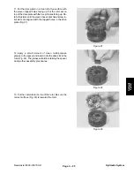
11. Remove the valve ring (Fig. 50). Remove and dis-
card the two seal rings (Fig. 51). The valve ring should
be free of nicks and scoring.
12. Remove the valve plate by lifting it from the isolation
manifold (Fig. 52).
13. Inspect the slot edges and ground surfaces. If the
valve plate shows nicks or scoring or the edges are not
sharp, it must be replaced.
NOTE: The valve ring and valve plate are a matched set
and must be replaced as a set.
Figure 50
Figure 51
Figure 52
Hydraulic System
Summary of Contents for REELMASTER 6500 D
Page 2: ...Reelmaster 6500 D 6700 D ...
Page 4: ...Reelmaster 6500 D 6700 D ...
Page 10: ...Reelmaster 6500 D 6700 D Page 1 6 Safety ...
Page 12: ...Reelmaster 6500 D 6700 D Page 2 2 Product Records and Manuals Equivalents and Conversions ...
Page 20: ...Rev C Reelmaster 6500 D 6700 D Page 2 10 Product Records and Manuals ...
Page 24: ...Rev C Reelmaster 6500 D 6700 D Page 2 14 Product Records and Manuals ...
Page 86: ...Engine Page 3 62 Reelmaster 6500 D 6700 D ...
Page 202: ...Reelmaster 6500 D 6700 D Page 5 8 2 Electrical System Rev C This page is intentionally blank ...
Page 226: ...Reelmaster 6500 D 6700 D Page 5 26 6 Electrical System Rev B This page is blank ...
Page 276: ...Reelmaster 6500 D 6700 D Page 6 22 Axles Planetaries and Brakes ...
Page 300: ...Reelmaster 6500 D 6700 D Page 7 24 Cutting Units Rev B Model 03853 Model 03854 Model 03855 ...


