Reelmaster 6500–D/6700–D
Page 4 – 86
Hydraulic System
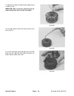
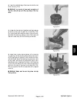
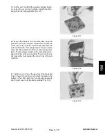
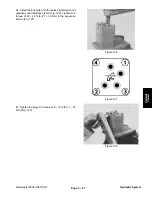
14. Align the five holes and press the five alignment pins
in place (Fig. 94).
IMPORTANT: Make sure the five alignment pins are
pressed below the surface of the commutator.
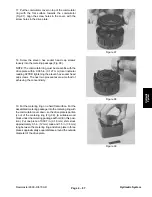
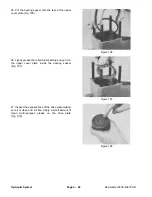
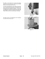
15. Put a few drops of oil into each recess in the commu-
tator (Fig. 95).
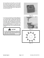
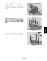
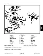
16. Put the commutator ring (either side up) on top of the
stator (Fig. 96). Align the commutator ring screw re-
cesses with the stator screw slots.
Figure 94
Figure 95
Figure 96
Summary of Contents for REELMASTER 6500 D
Page 2: ...Reelmaster 6500 D 6700 D ...
Page 4: ...Reelmaster 6500 D 6700 D ...
Page 10: ...Reelmaster 6500 D 6700 D Page 1 6 Safety ...
Page 12: ...Reelmaster 6500 D 6700 D Page 2 2 Product Records and Manuals Equivalents and Conversions ...
Page 20: ...Rev C Reelmaster 6500 D 6700 D Page 2 10 Product Records and Manuals ...
Page 24: ...Rev C Reelmaster 6500 D 6700 D Page 2 14 Product Records and Manuals ...
Page 86: ...Engine Page 3 62 Reelmaster 6500 D 6700 D ...
Page 202: ...Reelmaster 6500 D 6700 D Page 5 8 2 Electrical System Rev C This page is intentionally blank ...
Page 226: ...Reelmaster 6500 D 6700 D Page 5 26 6 Electrical System Rev B This page is blank ...
Page 276: ...Reelmaster 6500 D 6700 D Page 6 22 Axles Planetaries and Brakes ...
Page 300: ...Reelmaster 6500 D 6700 D Page 7 24 Cutting Units Rev B Model 03853 Model 03854 Model 03855 ...


