Reelmaster 6500–D/6700–D
Page 4 – 94
Hydraulic System
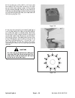
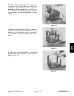
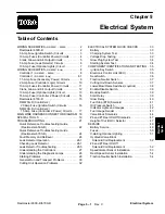
37. To install the valve plate correctly, first carefully
study Figures 93 and 94 for positioning of the valve plate
spring slots and other cavities in relation to the spring
and spring recesses on the isolation manifold. Be sure
to use the alignment grooves on the side of the isolation
manifold for orientation.
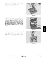
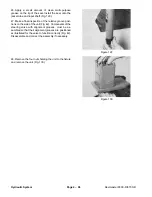
Put the valve plate with the surface that reads “shaft
side” down over the hex drive assembly. Align the three
spring slots centrally over the three springs installed in
the spring recesses of the isolation manifold. The valve
plate spring slot with the small cavity and the words “port
side” centrally below it (Fig. 118), must be placed over
the spring and spring recess in the isolation manifold at
the top (12 o’clock position) as shown (Fig. 118 and
101). Adjust the valve plate position radially to centralize
the spring slots over the springs and the spring recesses
in the isolation manifold.
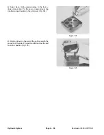
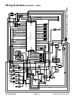
IMPORTANT: The unit will not function if the valve
plate is not positioned on the isolation manifold ex-
actly as shown in Figure 119. If the valve plate spring
slots, isolation manifold spring recesses and
springs are not centrally aligned in this step, the
springs could be damaged when the port manifold
is installed onto the assembly.
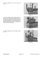
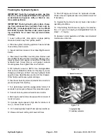
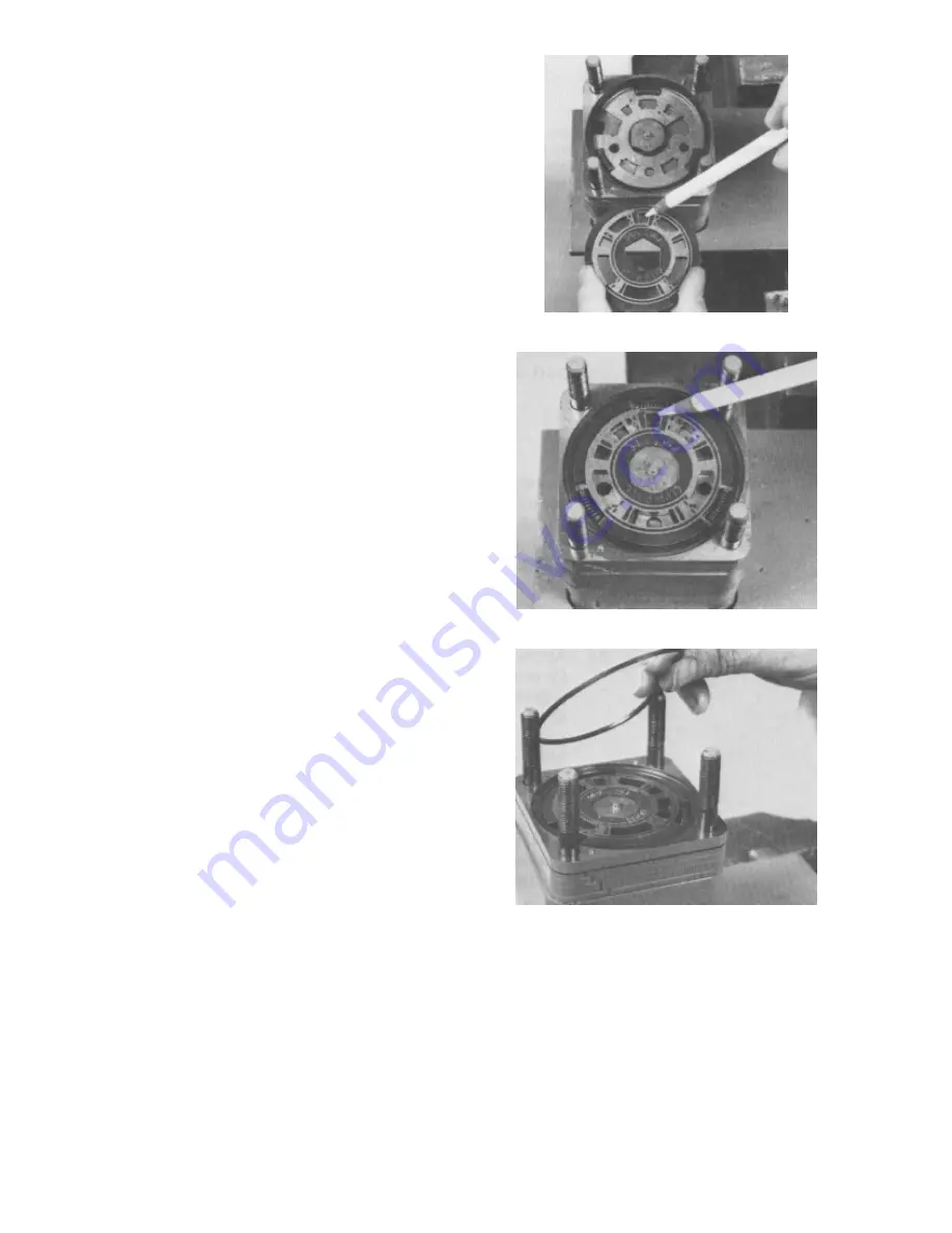
38. Apply clean multi–purpose grease to the valve ring
seal ring. Install the seal ring in the valve ring (Fig. 120).
Figure 118
Figure 119
Figure 120
Summary of Contents for REELMASTER 6500 D
Page 2: ...Reelmaster 6500 D 6700 D ...
Page 4: ...Reelmaster 6500 D 6700 D ...
Page 10: ...Reelmaster 6500 D 6700 D Page 1 6 Safety ...
Page 12: ...Reelmaster 6500 D 6700 D Page 2 2 Product Records and Manuals Equivalents and Conversions ...
Page 20: ...Rev C Reelmaster 6500 D 6700 D Page 2 10 Product Records and Manuals ...
Page 24: ...Rev C Reelmaster 6500 D 6700 D Page 2 14 Product Records and Manuals ...
Page 86: ...Engine Page 3 62 Reelmaster 6500 D 6700 D ...
Page 202: ...Reelmaster 6500 D 6700 D Page 5 8 2 Electrical System Rev C This page is intentionally blank ...
Page 226: ...Reelmaster 6500 D 6700 D Page 5 26 6 Electrical System Rev B This page is blank ...
Page 276: ...Reelmaster 6500 D 6700 D Page 6 22 Axles Planetaries and Brakes ...
Page 300: ...Reelmaster 6500 D 6700 D Page 7 24 Cutting Units Rev B Model 03853 Model 03854 Model 03855 ...


