Reelmaster 6500–D/6700–D
Page 4 – 98
Hydraulic System
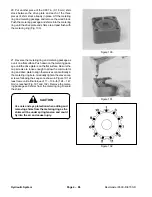
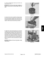
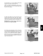
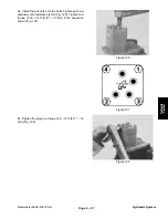
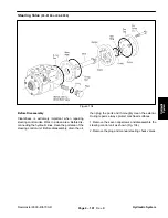
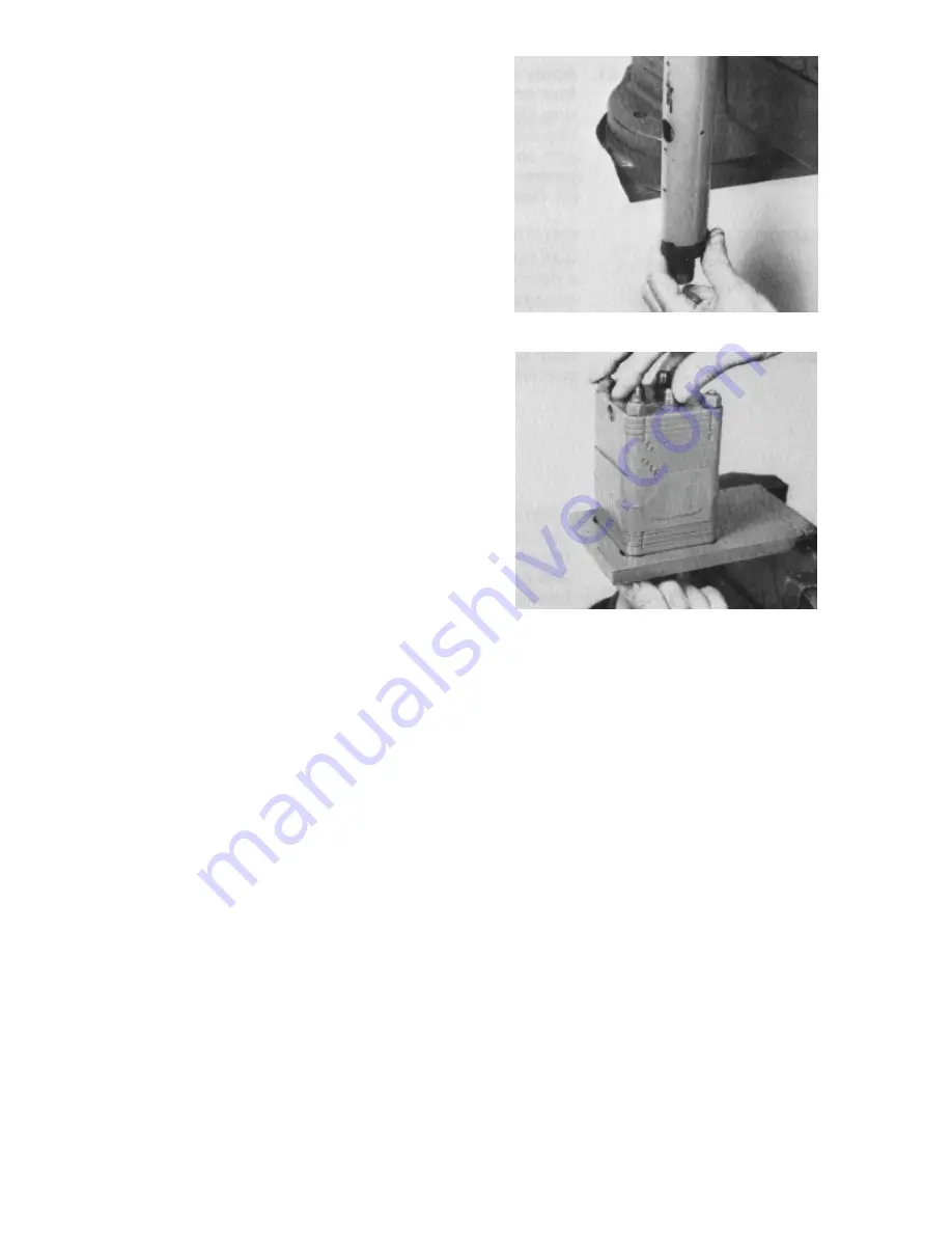
46. Apply a small amount of clean multi–purpose
grease on the lip of the seal. Install the seal onto the
jacket tube and input shaft (Fig. 129).
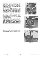
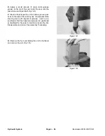
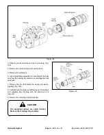
47. Make a final inspection of the relative groove posi-
tions on the side of the unit (Fig. 42). Components of the
steering valve with alignment grooves, must be as-
sembled so that their alignment grooves are positioned
as illustrated for the valve to function correctly (Fig. 42).
Disassemble and correct the assembly if necessary.
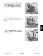
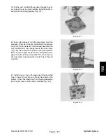
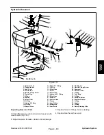
48. Remove the four nuts holding the unit to the fixture
and remove the unit (Fig. 130).
Figure 129
Figure 130
Summary of Contents for REELMASTER 6500 D
Page 2: ...Reelmaster 6500 D 6700 D ...
Page 4: ...Reelmaster 6500 D 6700 D ...
Page 10: ...Reelmaster 6500 D 6700 D Page 1 6 Safety ...
Page 12: ...Reelmaster 6500 D 6700 D Page 2 2 Product Records and Manuals Equivalents and Conversions ...
Page 20: ...Rev C Reelmaster 6500 D 6700 D Page 2 10 Product Records and Manuals ...
Page 24: ...Rev C Reelmaster 6500 D 6700 D Page 2 14 Product Records and Manuals ...
Page 86: ...Engine Page 3 62 Reelmaster 6500 D 6700 D ...
Page 202: ...Reelmaster 6500 D 6700 D Page 5 8 2 Electrical System Rev C This page is intentionally blank ...
Page 226: ...Reelmaster 6500 D 6700 D Page 5 26 6 Electrical System Rev B This page is blank ...
Page 276: ...Reelmaster 6500 D 6700 D Page 6 22 Axles Planetaries and Brakes ...
Page 300: ...Reelmaster 6500 D 6700 D Page 7 24 Cutting Units Rev B Model 03853 Model 03854 Model 03855 ...


