Rev. B
Reelmaster 6500–D/6700–D
Page 5 – 28
Electrical System
Understanding the Diagnostic Lamps
Controller #1 (Primary) Fault
Identification / Operator Warning
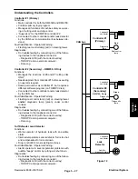
The reel control lamp (red) on the steering tower will stay
ON with no flashing if:
1. The glow plugs are on.
2. Operator mowing too slow or too fast for proper
ClipAce control.
3. Defective reel speed sensor (reels engaged).
4. Defective traction unit speed sensor (reels en-
gaged – cannot sense ground speed).
The reel control lamp (red) on the steering tower will
flash ON and OFF if:
1. Number of reel blades is not programmed at set–up
(reels will backlap but not run forward).
2. Programmed speed limit (LIMITMPH) has been ex-
ceeded (reels will also shut off).
3. Controller senses an OUTPUT fault (open or
shorted condition) with controller #1 or controller #2
(RM6700 only – see next section).
4. Controller shut down reels during backlap (Control-
ler sensed a reel speed of less than 50 RPM).
Controller #2 (Secondary) Fault
Identification / Operator Warning (RM6700–D only)
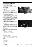
The diagnostic lamp (green) under the control console
will stay steady if:
1. Controller #2 program is successfully loaded (from
#1) and read to operate (all O.K.).
A flashing reel control lamp (red) on steering tower AND
a flashing diagnostic lamp (green) under control console
indicates:
1. Controller #2 senses an OUTPUT fault (open or
shorted condition).
NO reel control lamp (red) on steering tower AND a
flashing diagnostic lamp (green) under control console
indicates:
1. Program fault with controller #1.
2. Possible fault with the CAN bus (wiring problem –
no communication between controllers).
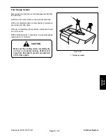
Turf Defender Leak Detector
The audible alarm indicates:
1. ONE short beep at start–up. Detector has com-
pleted internal test and is operating properly.
2. FOUR short beeps. Detector is indicating a problem
such as:
– Low oil.
– Air leak.
– Internal problem.
– Oil overheat.
3. LONG beeps and reels shut off. Leak has been de-
tected.
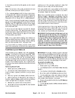
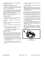
1. Reel control lamp (Controller #1)
1
Figure 13
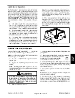
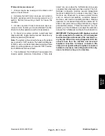
1. (#2) Electronic Controller Light
Figure 14
1
Summary of Contents for REELMASTER 6500 D
Page 2: ...Reelmaster 6500 D 6700 D ...
Page 4: ...Reelmaster 6500 D 6700 D ...
Page 10: ...Reelmaster 6500 D 6700 D Page 1 6 Safety ...
Page 12: ...Reelmaster 6500 D 6700 D Page 2 2 Product Records and Manuals Equivalents and Conversions ...
Page 20: ...Rev C Reelmaster 6500 D 6700 D Page 2 10 Product Records and Manuals ...
Page 24: ...Rev C Reelmaster 6500 D 6700 D Page 2 14 Product Records and Manuals ...
Page 86: ...Engine Page 3 62 Reelmaster 6500 D 6700 D ...
Page 202: ...Reelmaster 6500 D 6700 D Page 5 8 2 Electrical System Rev C This page is intentionally blank ...
Page 226: ...Reelmaster 6500 D 6700 D Page 5 26 6 Electrical System Rev B This page is blank ...
Page 276: ...Reelmaster 6500 D 6700 D Page 6 22 Axles Planetaries and Brakes ...
Page 300: ...Reelmaster 6500 D 6700 D Page 7 24 Cutting Units Rev B Model 03853 Model 03854 Model 03855 ...

