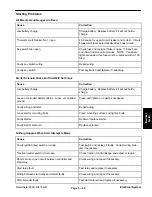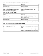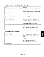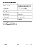
Reelmaster 6500–D/6700–D
Page 5 – 38
Electrical System
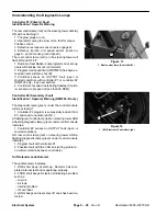
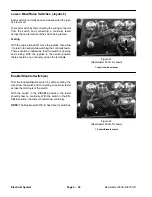
Lower–Mow/Raise Switches (Joystick)
Each switch is normally open and closes when the joys-
tick is moved.
Test each switch by disconnecting the wiring connector
from the switch and connecting a continuity tester
across the two terminals of the switch being tested.
Testing
With the engine turned off, move the joystick, then allow
it to return to neutral while watching the continuity tester.
There should be indications that the switch is opening
and closing. With the joystick in the neutral position
there should be no continuity across the terminals.
1
Figure 21
(Reelmaster 6500–D shown)
1. Joystick with switches
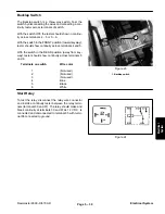
Enable/Disable Switch(es)
Test the Enable/Disable switch by disconnecting the
wires from the switch and connecting a continuity tester
across the terminals of the switch.
With the switch in the DISABLE position, the tester
should show no continuity. With the switch in the EN-
ABLE position, the tester should show continuity.
NOTE: The Reelmaster 6700–D has three (3) switches.
1
Figure 22
(Reelmaster 6500–D shown)
1. Enable/Disable switch
Summary of Contents for REELMASTER 6500 D
Page 2: ...Reelmaster 6500 D 6700 D ...
Page 4: ...Reelmaster 6500 D 6700 D ...
Page 10: ...Reelmaster 6500 D 6700 D Page 1 6 Safety ...
Page 12: ...Reelmaster 6500 D 6700 D Page 2 2 Product Records and Manuals Equivalents and Conversions ...
Page 20: ...Rev C Reelmaster 6500 D 6700 D Page 2 10 Product Records and Manuals ...
Page 24: ...Rev C Reelmaster 6500 D 6700 D Page 2 14 Product Records and Manuals ...
Page 86: ...Engine Page 3 62 Reelmaster 6500 D 6700 D ...
Page 202: ...Reelmaster 6500 D 6700 D Page 5 8 2 Electrical System Rev C This page is intentionally blank ...
Page 226: ...Reelmaster 6500 D 6700 D Page 5 26 6 Electrical System Rev B This page is blank ...
Page 276: ...Reelmaster 6500 D 6700 D Page 6 22 Axles Planetaries and Brakes ...
Page 300: ...Reelmaster 6500 D 6700 D Page 7 24 Cutting Units Rev B Model 03853 Model 03854 Model 03855 ...

