Reelmaster 6500–D/6700–D
Page 5 – 40
Electrical System
Glow Relay and Glow Plugs
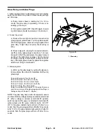
1. Attach an amp meter to glow plug circuit. Turn ignition
switch to ON. Meter may have an initial reading as high
as 100 amps.
A. If amp meter shows a reading for 5 to 12 se-
conds, the glow relay is operating. If there is no
reading, go to step 2.
B. Turn ignition switch OFF, then ON again. A read-
ing of 48 amps should be observed. Go to step 3.
2. To test the circuit.
A. Check with a test light at buss bar connection for
glow plugs at cylinder head. Turn the ignition switch
ON. If the light glows, power is being supplied from
glow relay. If light does not glow check wiring or
relay.
B. Check relay with a test light connected at termi-
nal #5 on relay (glow plugs connection). Turn igni-
tion switch ON. If the light glows, the power relay is
working. If the light does not glow, check for power
to relay by moving to terminal #1 (power from bat-
tery). If the light glows, check for power from ignition
switch by moving to terminal #3.
3. Glow plug test:
A. Warm up the glow plugs by cycling the glow sys-
tem two times, then check for total draw of all four (4)
glow plugs:
if draw is 48 amps all four (4) are OK.
if draw is 36 amps, then one (1) is faulty.
if draw is 24 amps, then two (2) are faulty.
if draw is 12 amps, then three (3) are faulty.
if draw is 0 amps, then all are faulty.
if draw is more than 48 amps (60 to 100 amps) there is a
short in one or more of the glow plugs (see Glow Plugs in
Testing section of Chapter 3 – Engine.)
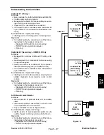
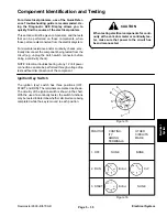
NOTE: The glow relay has a built in temperature sensor
and timer. Battery voltage is always available at terminal
#1. When voltage is sensed at terminal #3 (ignition
switch turned to ON) power is directed to terminals #5
(glow plugs) and #6 (glow indicator light). At 68
_
F
(20
_
C) the glow indicator light will turn off after 5 se-
conds, then the glow plugs will turn off after 12 seconds.
At 32
_
F (0
_
C) the glow indicator light will turn off after 10
seconds, then the glow plugs will turn off after 18 se-
conds.
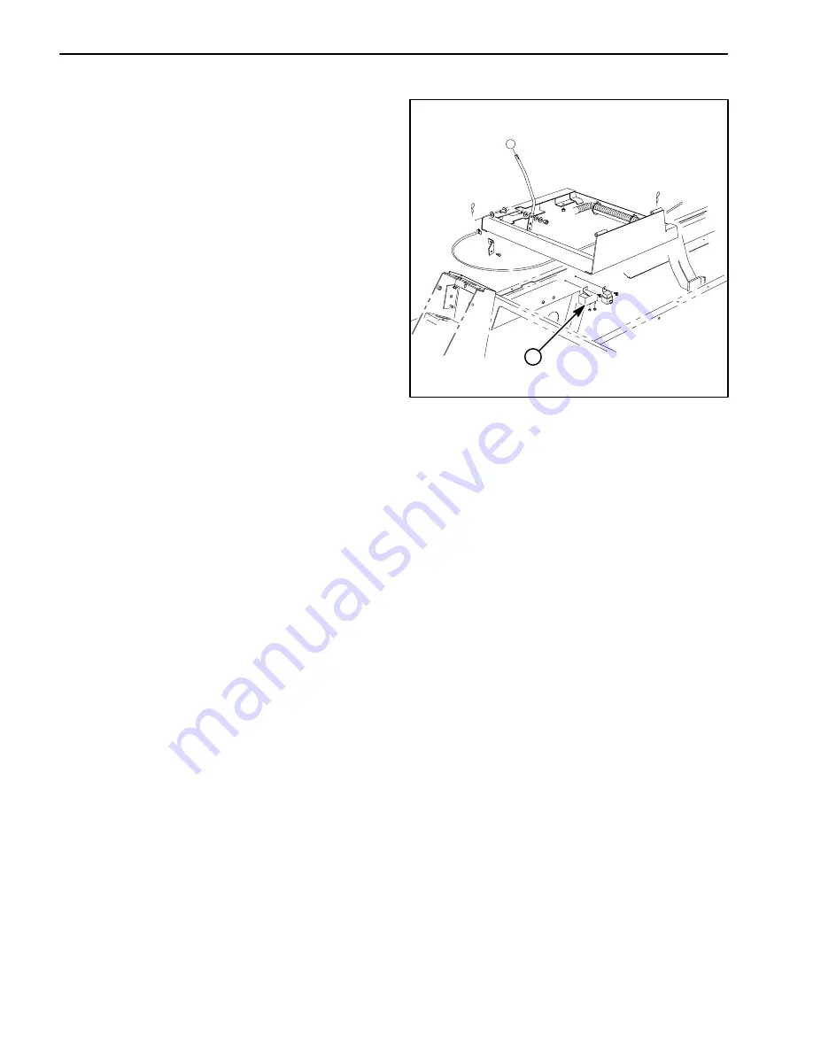
1
Figure 25
1. Glow relay
Summary of Contents for REELMASTER 6500 D
Page 2: ...Reelmaster 6500 D 6700 D ...
Page 4: ...Reelmaster 6500 D 6700 D ...
Page 10: ...Reelmaster 6500 D 6700 D Page 1 6 Safety ...
Page 12: ...Reelmaster 6500 D 6700 D Page 2 2 Product Records and Manuals Equivalents and Conversions ...
Page 20: ...Rev C Reelmaster 6500 D 6700 D Page 2 10 Product Records and Manuals ...
Page 24: ...Rev C Reelmaster 6500 D 6700 D Page 2 14 Product Records and Manuals ...
Page 86: ...Engine Page 3 62 Reelmaster 6500 D 6700 D ...
Page 202: ...Reelmaster 6500 D 6700 D Page 5 8 2 Electrical System Rev C This page is intentionally blank ...
Page 226: ...Reelmaster 6500 D 6700 D Page 5 26 6 Electrical System Rev B This page is blank ...
Page 276: ...Reelmaster 6500 D 6700 D Page 6 22 Axles Planetaries and Brakes ...
Page 300: ...Reelmaster 6500 D 6700 D Page 7 24 Cutting Units Rev B Model 03853 Model 03854 Model 03855 ...


