Reelmaster 6500–D/6700–D
Page 5 – 42
Electrical System
Indicator Lights and Gauges
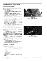
Reel Control and Diagnostic Lamps
See Quick Reference Troubleshooting Guide in
Troubleshooting section for explanation of diagnostic
functions.
The REEL CONTROL lamp should come ON when the
cutting units are operating with the machine not moving.
When the light is ON, it indicates that the machine is be-
ing operated in a way in which the automatic reel speed
control cannot obtain the desired clip.
Test the lamps by disconnecting the wires and applying
12 V.D.C. between the lamp wiring terminals.
Oil Pressure Light
Oil pressure lamp should come on when the ignition key
switch is in the RUN position with the engine not running
or if the oil pressure switch closes during operation – oil
pressure below 7 psi (0.5 kg/cm
2
).
Test the lamp by grounding the wire that is connected to
the oil pressure switch. The light should come on when
the wire is grounded (with the key switch on and engine
not running).
Charge Light
The charge light should come on when the ignition key
switch is in the RUN position with the engine not running
or if the charging circuit is not operating properly during
operation.
Glow Light
The glow light should be on when the ignition switch is
in the ON position. The glow system runs off of a timer
relay.
Temperature Light
The temperature light should come on only if the high
temperature shut–down switch has stopped the engine
– coolant temperature above 225
_
F (108
_
C).
Test the lamp by grounding the wire that is connected to
the high temperature shut–down switch. The light
should come on when the wire is grounded.
Water in Fuel Light
Indicates water in fuel system. Switch is located on fuel
filter/water separator.
Lower Water Level Light
Indicates coolant level is low. Switch is located on de-
gassing tank.
Hourmeter
Test the hourmeter by connecting a 12 volt battery so the
positive (+) battery terminal is connected to the positive
terminal on the hourmeter. Connect the negative (–) bat-
tery terminal to the negative (–) terminal on the alterna-
tor. The hourmeter should operate as 12 V.D.C. is
applied between the terminals.
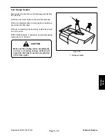
Temperature Gauge, Fuel Level Gauge and
Speedometer
To test a gauge, use a commercial gauge tester. If a
commercial gauge tester is not available, substitute a
new gauge or test the sending unit.
Summary of Contents for REELMASTER 6500 D
Page 2: ...Reelmaster 6500 D 6700 D ...
Page 4: ...Reelmaster 6500 D 6700 D ...
Page 10: ...Reelmaster 6500 D 6700 D Page 1 6 Safety ...
Page 12: ...Reelmaster 6500 D 6700 D Page 2 2 Product Records and Manuals Equivalents and Conversions ...
Page 20: ...Rev C Reelmaster 6500 D 6700 D Page 2 10 Product Records and Manuals ...
Page 24: ...Rev C Reelmaster 6500 D 6700 D Page 2 14 Product Records and Manuals ...
Page 86: ...Engine Page 3 62 Reelmaster 6500 D 6700 D ...
Page 202: ...Reelmaster 6500 D 6700 D Page 5 8 2 Electrical System Rev C This page is intentionally blank ...
Page 226: ...Reelmaster 6500 D 6700 D Page 5 26 6 Electrical System Rev B This page is blank ...
Page 276: ...Reelmaster 6500 D 6700 D Page 6 22 Axles Planetaries and Brakes ...
Page 300: ...Reelmaster 6500 D 6700 D Page 7 24 Cutting Units Rev B Model 03853 Model 03854 Model 03855 ...

