Reelmaster 6500–D/6700–D
Page 5 – 51
Electrical System
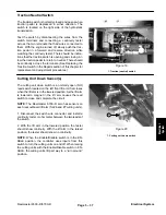
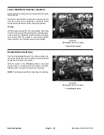
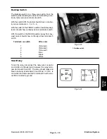
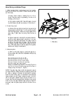
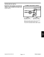
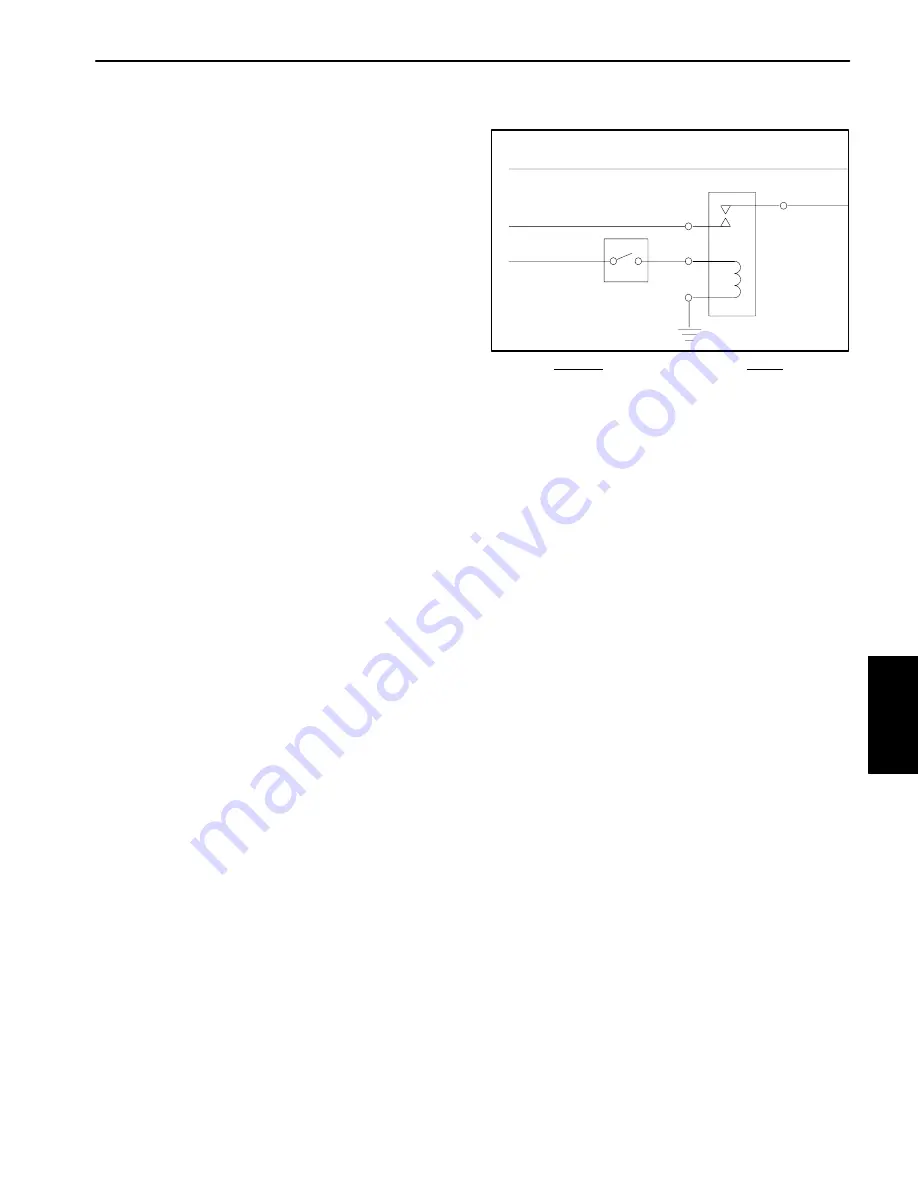
Installing Optional Lighting
IMPORTANT: If optional lighting is to be added to the
traction unit, use the following schematic and part
numbers to prevent damage to the traction unit’s
electrical system.
Switch
Relay
Orange
Red
Black
2
3
86
85
30
30
To Lights w/external ground
To Lights
SCHEMATIC FOR OPTIONAL LIGHTING
Switch*
Relay
Toro Part No. 75–1010
Honeywell Part No. 1TL1–2
Toro Part No. 70–1480
Bosch Part No. 0–332–204
* Punch out in control panel provided for switch installation
Add 10 Amp fuse to fuse block at location shown
Black, red and orange wires are located in control console.
Electrical System
Summary of Contents for REELMASTER 6500 D
Page 2: ...Reelmaster 6500 D 6700 D ...
Page 4: ...Reelmaster 6500 D 6700 D ...
Page 10: ...Reelmaster 6500 D 6700 D Page 1 6 Safety ...
Page 12: ...Reelmaster 6500 D 6700 D Page 2 2 Product Records and Manuals Equivalents and Conversions ...
Page 20: ...Rev C Reelmaster 6500 D 6700 D Page 2 10 Product Records and Manuals ...
Page 24: ...Rev C Reelmaster 6500 D 6700 D Page 2 14 Product Records and Manuals ...
Page 86: ...Engine Page 3 62 Reelmaster 6500 D 6700 D ...
Page 202: ...Reelmaster 6500 D 6700 D Page 5 8 2 Electrical System Rev C This page is intentionally blank ...
Page 226: ...Reelmaster 6500 D 6700 D Page 5 26 6 Electrical System Rev B This page is blank ...
Page 276: ...Reelmaster 6500 D 6700 D Page 6 22 Axles Planetaries and Brakes ...
Page 300: ...Reelmaster 6500 D 6700 D Page 7 24 Cutting Units Rev B Model 03853 Model 03854 Model 03855 ...

